
Rotary cylindrical garbage storage bin leachate guide device

A diversion device, rotary technology, applied in the direction of filtration separation, mobile filter element filter, separation method, etc., can solve the problems of increasing the difficulty and cost of concrete structure processing, high work intensity, high investment cost, etc., to achieve the benefit of storage Effects of wall concrete structure treatment, reduction in the number and area of ​​openings, and reduction in labor costs

Pending Publication Date: 2020-01-31
上海市机电设计研究院有限公司
View PDF0 Cites 4 Cited by
  • Summary
  • Abstract
  • Description
  • Claims
  • Application Information

AI Technical Summary

Problems solved by technology

Judging from the actual operation effect, the grid hole blockage will reappear soon, and the manual operation is very frequent; at the same time, since the fixed grid is at the bottom of the garbage storage bin, the operation is more difficult
Moreover, because the landfill leachate includes the water contained in the waste itself and the high-concentration organic wastewater generated during the waste degradation process, it has the characteristics of complex components, high concentration, large chroma, and strong toxicity. Toxic gas, there is a certain potential safety hazard, so the operator is facing a very harsh environment, and the work intensity is very high
[0004] In addition, due to the consideration of the processing volume of the blocking material, the area of ​​the fixed grid is large, and it is generally made of stainless steel, so the investment cost is very high; at the same time, the large area of ​​the fixed grid also increases the cost of the garbage storage bin wall. Difficulty and expense of handling concrete structures

Method used


Image

  • Rotary cylindrical garbage storage bin leachate guide device
  • Rotary cylindrical garbage storage bin leachate guide device
  • Rotary cylindrical garbage storage bin leachate guide device

Examples


Embodiment Construction

[0030] The present invention will be further described below in conjunction with the accompanying drawings and specific embodiments.

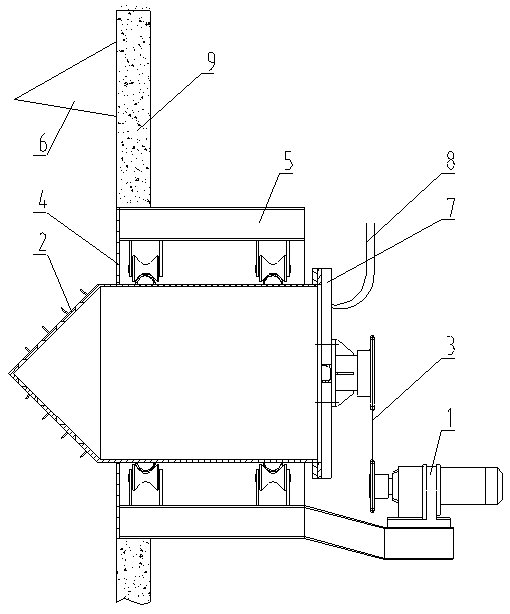
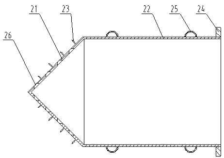
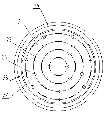
[0031] Please see attached figure 1 , a rotary cylindrical garbage storage bin leachate diversion device, including a rotating transmission assembly, a rotary diversion tube assembly 2, a sealing baffle 4 and a base 5; There are reserved holes, the inner end of the base 5 is matched and embedded in the reserved hole, and the outer end of the base 5 is fixed in the maintenance channel outside the garbage bin; please refer to the attached figure 2 And attached image 3 , the rotary guide tube assembly 2 includes a garbage intrusion disc 21, a rotary guide tube 22, a blade 23 and a leachate hole 26, the rotary guide tube 22 runs through the base 5 coaxially, and the garbage intrusion disc 21 is in a conical structure And coaxially connected to the inner end of the rotary guide tube 22, the garbage intrusion disc 21 is located in the garbage sto...


PUM


Abstract

The invention discloses a rotary type cylindrical garbage storage bin leachate guide device which comprises a rotary transmission assembly, a rotary type guide cylinder assembly (2), a sealing baffle(4) and a base (5); the inner end of the base is installed on a bin wall (9) through a preformed hole and extends into a maintenance channel outside the bin; the rotary type guide cylinder assembly (2) comprises a garbage inrush disc (21), a rotary guide cylinder (22), blades (23) and a leachate hole (26); the garbage inrush disc is of a conical structure, is connected with the rotary guide cylinder in parallel and is located in the bin; a cutterhead and the leachate hole are formed in the garbage inrush disc, and the rotary guide cylinder rotates in the base through the rotary transmission assembly; and the sealing baffle seals and blocks a gap between the rotary guide cylinder and the base. The blades arranged on the conical garbage inrush disc can be driven by the rotation of the rotaryguide cylinder to poke up morphological garbage in the storage bin, movement of garbage in a local area is triggered, the arch breaking effect is achieved, and it is guaranteed that leachate flows smoothly.

Description

technical field [0001] The invention relates to equipment used in a domestic garbage treatment plant, in particular to a leachate diversion device for a rotating cylindrical garbage storage bin. Background technique [0002] With the continuous maturity and reliable application of domestic waste incineration power generation technology, domestic and foreign domestic waste incineration power plant (field) models have been actively promoted, and construction projects are increasing. [0003] Garbage storage bins are installed in the pre-treatment section of domestic waste incineration power plants (fields) to receive and store domestic waste transported from abroad. On the side wall of the bottom of the garbage storage bin, usually according to the volume of the garbage pool, one or two rows of fixed grids and other structures are arranged to facilitate the outflow of the garbage leachate. The garbage leachate flows into the leachate pool through the maintenance channel trench...

Claims


Application Information

Patent Timeline
IPC IPC(8): B01D33/073B02C18/00B02C18/14B02C18/18B02C18/24
CPCB01D33/073B02C18/0092B02C18/14B02C18/18B02C18/24B02C2201/06
Inventor 杨富强王小弟斯信忠雍士玮刘志鹏谢一津俞星豪杨岳青袁新罗洪连
Owner 上海市机电设计研究院有限公司
Learn More