
Metal shell cinder ladle structure

A metal shell and shell technology, applied in the field of injection molding, can solve the problems of reduced yield and high thermal stress, and achieve the effect of small probability of damage and deformation, small thermal stress, and improved product ratio

Inactive Publication Date: 2020-01-31
深圳市人和智聚科技开发有限公司
View PDF0 Cites 0 Cited by
  • Summary
  • Abstract
  • Description
  • Claims
  • Application Information

AI Technical Summary

Problems solved by technology

[0002] During the production process of the metal shell, it is necessary to design the structure of the slag bag so that the fluid can be filled into various parts of the product. If the design of the slag bag structure is unreasonable, high thermal stress will be generated, resulting in a decrease in the yield

Method used


Image

  • Metal shell cinder ladle structure
  • Metal shell cinder ladle structure
  • Metal shell cinder ladle structure

Examples


Embodiment Construction

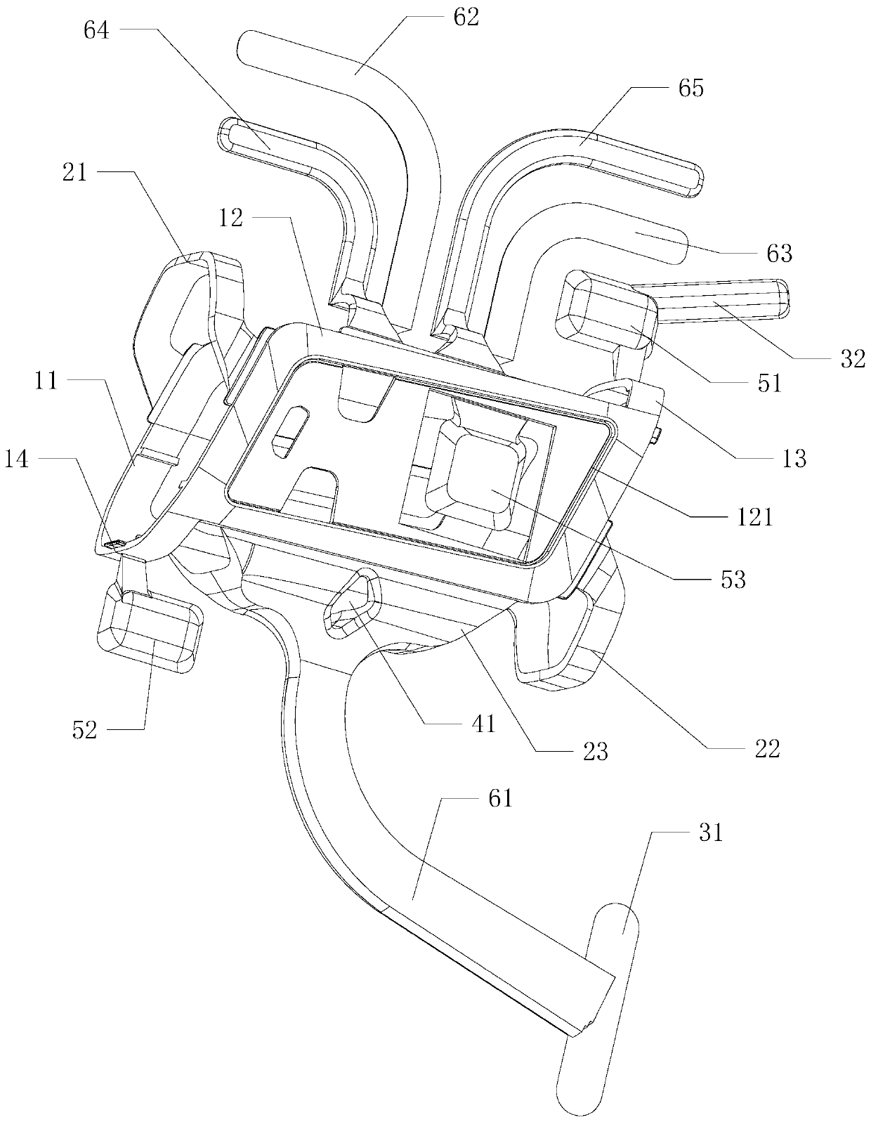
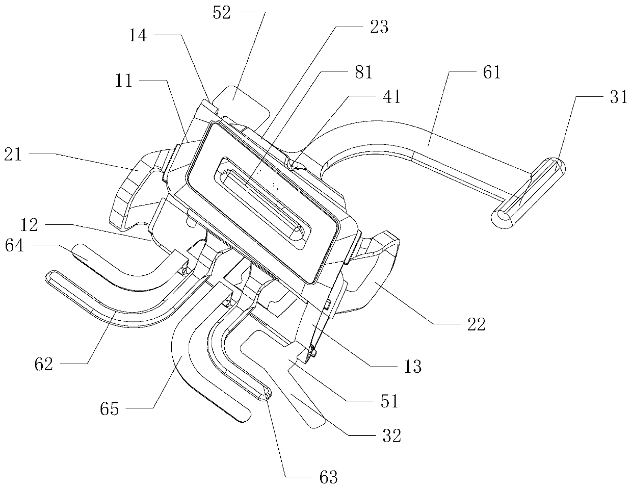
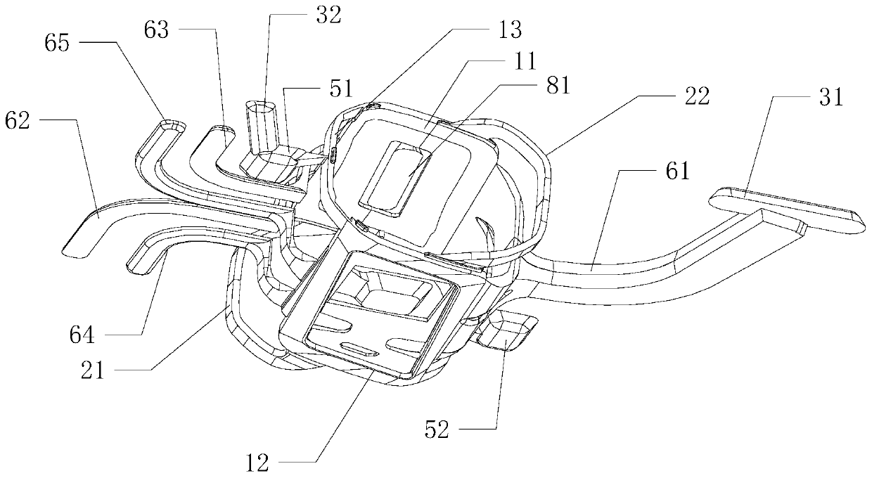
[0032] Attached below Figure 1~4 The slag ladle structure of a metal shell of the present invention will be further described.

[0033] A slag clad structure of a metal shell, the shell includes an upper shell 11 and a lower shell 12, and the right corners of the front sides of the upper shell 11 and the lower shell 12 are provided with a joint connecting the upper shell 11 and the lower shell 12 The first connecting rib 13, the left corner of the rear side of the upper casing 11 and the lower casing 12 is provided with the second connecting rib 14 connecting the upper casing 11 and the lower casing 12, the upper casing 11 and the lower casing 12 The left corner of the front side is provided with the first garbage bag connecting rib 21 connecting the upper casing 11 and the lower casing 12, and the right corner of the rear side of the upper casing 11 and the lower casing 12 is provided with a connecting rib 21 connecting the upper casing 11 and the lower casing. The second g...


PUM


Abstract

The invention relates to a metal shell cinder ladle structure. A shell comprises an upper shell body and a lower shell body. First connecting ribs for connecting the upper shell body and the lower shell body are arranged at the right corners of the front sides of the upper shell body and the lower shell body, second connecting ribs for connecting the upper shell body and the lower shell body are arranged at the left corners of the rear sides of the upper shell body and the lower shell body, first waste ladle connecting ribs for connecting the upper shell body and the lower shell body are arranged at the left corners of the front sides of the upper shell body and the lower shell body, and second waste ladle connecting ribs for connecting the upper shell body and the lower shell body are arranged at the right corners of the right sides of the upper shell body and the lower shell body. The first waste ladle connecting ribs and the second waste ladle connecting ribs are symmetrically arranged relative to the diagonal plants of the upper shell body and the lower shell body from the left back corner to the front right corner. By designing the first waste ladle connecting ribs and the second waste ladle connecting ribs generally symmetric about the first connecting ribs and the second connecting ribs, the metal shell can be generally symmetric in the injection molding process, thermalstress is small, the probability of destruction and deformation is small, and the finished product ratio is increased.

Description

technical field [0001] The invention relates to the technical field of injection molding, in particular to a slag bag structure of a metal shell. Background technique [0002] During the manufacturing process of the metal shell, the structure of the slag bag needs to be designed so that the fluid can be filled into various parts of the product. If the design of the slag bag structure is not reasonable, high thermal stress will be generated, resulting in a decrease in the yield. Contents of the invention [0003] The technical problem to be solved by the present invention is to propose a slag bag structure of the metal shell, so that the metal shell can be roughly symmetrical during the injection molding process, the thermal stress is small, the probability of damage and deformation is small, and the finished product rate is improved. [0004] A slag clad structure of a metal shell, the shell includes an upper shell and a lower shell, the right corners of the front sides of...

Claims


Application Information

Patent Timeline
IPC IPC(8): B22D17/22
CPCB22D17/22
Inventor 霍新会
Owner 深圳市人和智聚科技开发有限公司
Learn More