

Commutator segment for commutator and production equipment of commutator segment
A technology for production equipment and commutator segments, which is applied in the field of commutator segments and its production equipment, can solve problems such as shortening the service life of motors, uneven load current density, and damage to enameled wires, so as to improve rectification quality, reduce mutual interference, and increase The effect of intertwined spaces
- Summary
- Abstract
- Description
- Claims
- Application Information
AI Technical Summary
Problems solved by technology
Method used
Image

Examples
Embodiment 1
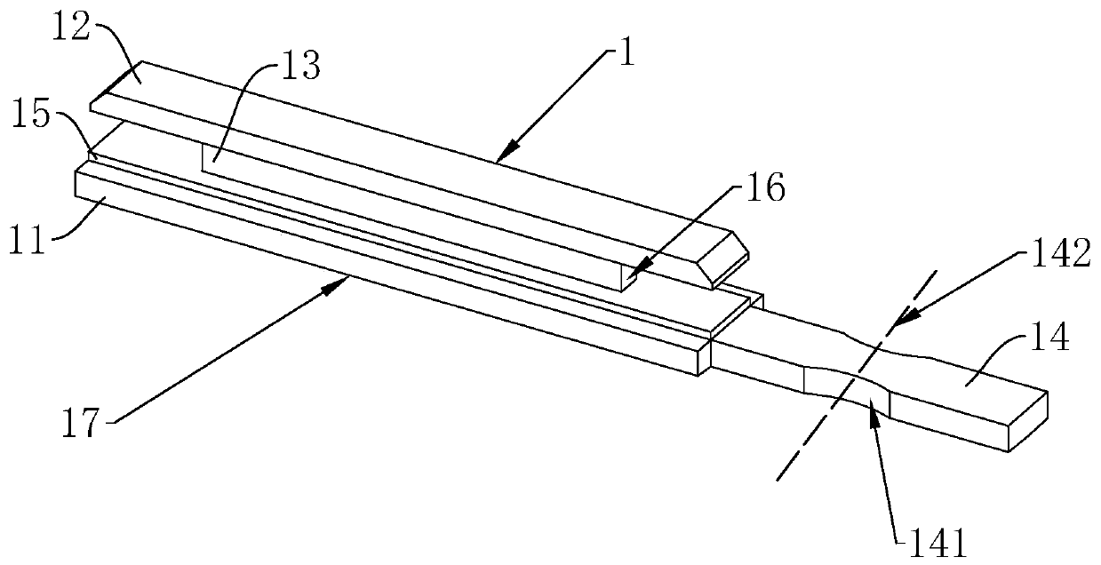
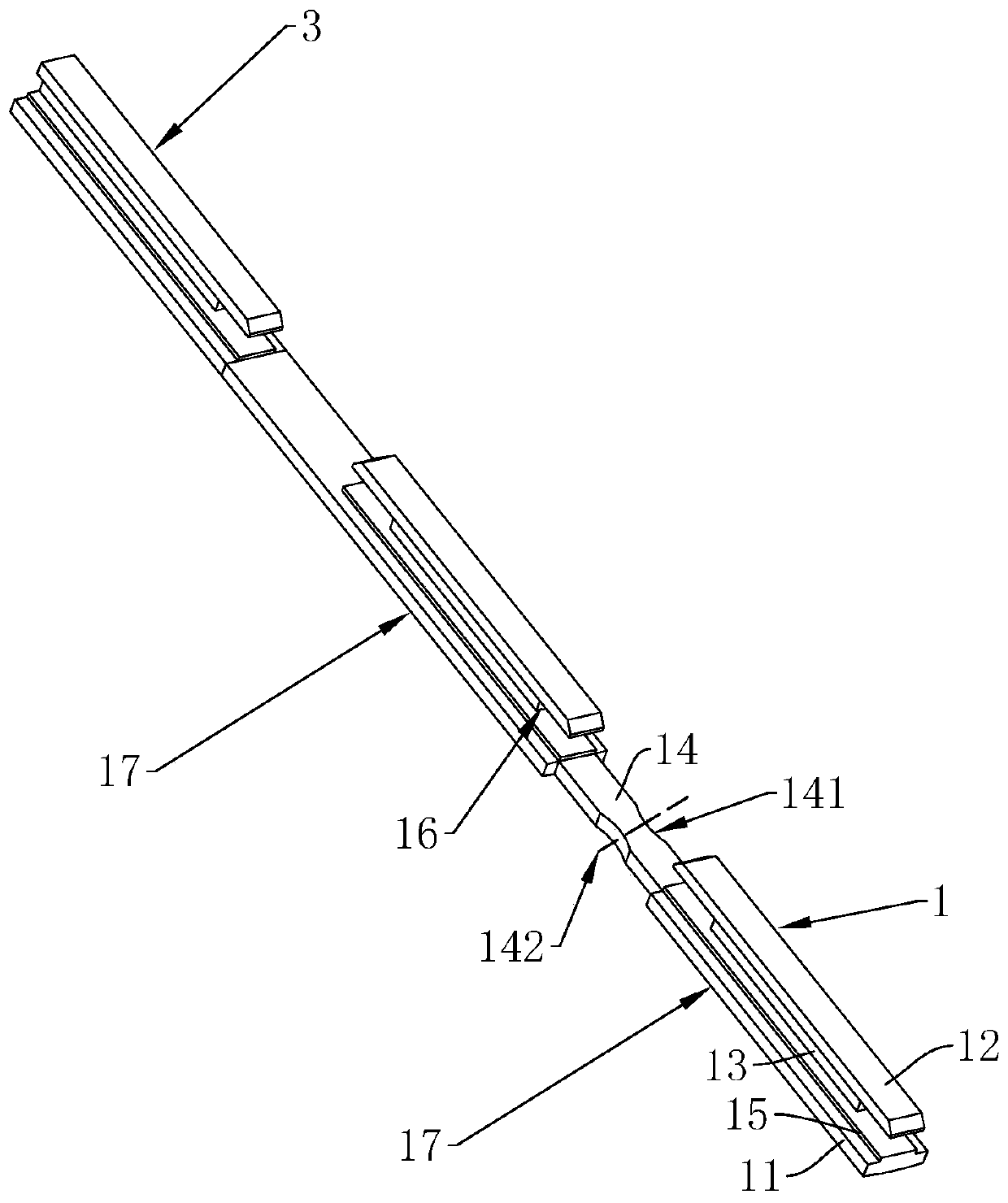
[0046] refer to figure 1 , is a commutator segment 1 for a commutator 2 disclosed in the present invention, including a segment body 17 and a hook portion 14 . The sheet body 17 includes a contact block 11 and a clamping block 12. The contact block 11 is a cuboid and is provided with a connecting block 15 along its length. 13 is fixedly connected to the clamping block 12 at one end away from the connecting block 15, the length of the connecting piece 13 is less than the length of the contact block 11 and the clamping block 12, the contact block 11, the connecting block 15, the connecting piece 13 and the clamping block 12 are integrally formed, and the sheet body 17 The overall shape is I-shaped, which is convenient for the commutator segment 1 to be assembled into the commutator 2 . The hook portion 14 is a cuboid and one end along its length direction is fixedly connected with the contact block 11. Both ends of the hook portion 14 along its width direction are provided with...
Embodiment 2
[0051] refer to figure 2 with Figure 4 , is a kind of production equipment applied to the commutator segment 1 in the embodiment 1 disclosed by the present invention, including a body 61, a stamping cover plate 5 and a stamping die 4, and the body 61 is provided with a punch 62 moving in the vertical direction, The bottom of the punch 62 is connected with the stamping cover plate 5, and the stamping die 4 is located directly below the stamping cover plate 5 and fits with the stamping cover plate 5. The outer wall of the stamping die 4 is provided with a feeding hole 47, and the feeding hole 47 is conveyed with The elongated profile 3, in this embodiment, the elongated profile 3 is formed by drawing a elongated silver-copper alloy. The punch 62 applies pressure to the stamping cover plate 5 , and then stamps the elongated profile 3 in the stamping die 4 below.
[0052] refer to Figure 5 , the top of the stamping die 4 is successively provided with the first punching groov...
Embodiment 3
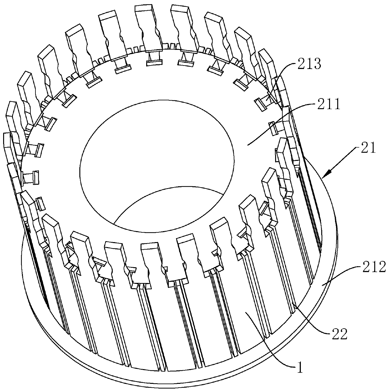
[0061] refer to Figure 10 , the difference from Embodiment 1 is that the section of the two deformation grooves 141 on the commutator piece 1 is isosceles trapezoidal, and the two deformation grooves 141 run through the upper and lower end surfaces of the hook portion 14, and the straight-line distance between the bottoms of the two deformation grooves 141 It is also 1.03 mm, and the setting of the deformation groove 141 with an isosceles trapezoidal cross-section can also reduce the protrusion and burr caused by the pressure on both sides of the hook part 14 when it is bent. The distance between the commutator segments 1 further increases the space for the enameled wires to wind around the commutator segments 1 and reduces the mutual interference between the enameled wires. When processing the commutator segment 1 in this embodiment, it is only necessary to change the shape of the fifth stamping cutter head 53 on the stamping cover plate 5 to a shape matching the deformation...
PUM
| Property | Measurement | Unit |
|---|---|---|
| Length | aaaaa | aaaaa |
Abstract
Description
Claims
Application Information