Gas pressure limiting valve with annular gap seat for controlling and discharging a gaseous medium

A gas pressure and gaseous medium technology, applied in the field of pressure limiting valves, can solve problems such as low medium flow, damage, and time-consuming pressure drop, and achieve the effects of improving life, reducing system overpressure, and reducing system pressure

Active Publication Date: 2020-01-31
ROBERT BOSCH GMBH
View PDF7 Cites 1 Cited by
  • Summary
  • Abstract
  • Description
  • Claims
  • Application Information

AI Technical Summary

Problems solved by technology

[0004] The pressure limiting valve known from DE 10 2013 204 563 A1 may have certain disadvantages
[0005] Only a small flow cross-section is formed when the pressure-limiting valve opens only slightly and thus has a small opening stroke, which results in a low medium flow
This has the result that only a small amount of medium can flow out when opening the pressure limiting valve, especially in the initial phase of opening, and thus the pressure drop in the system requires a very high time-consuming
[0006] A further disadv

Method used


Image

  • Gas pressure limiting valve with annular gap seat for controlling and discharging a gaseous medium
  • Gas pressure limiting valve with annular gap seat for controlling and discharging a gaseous medium
  • Gas pressure limiting valve with annular gap seat for controlling and discharging a gaseous medium

Examples


Embodiment Construction

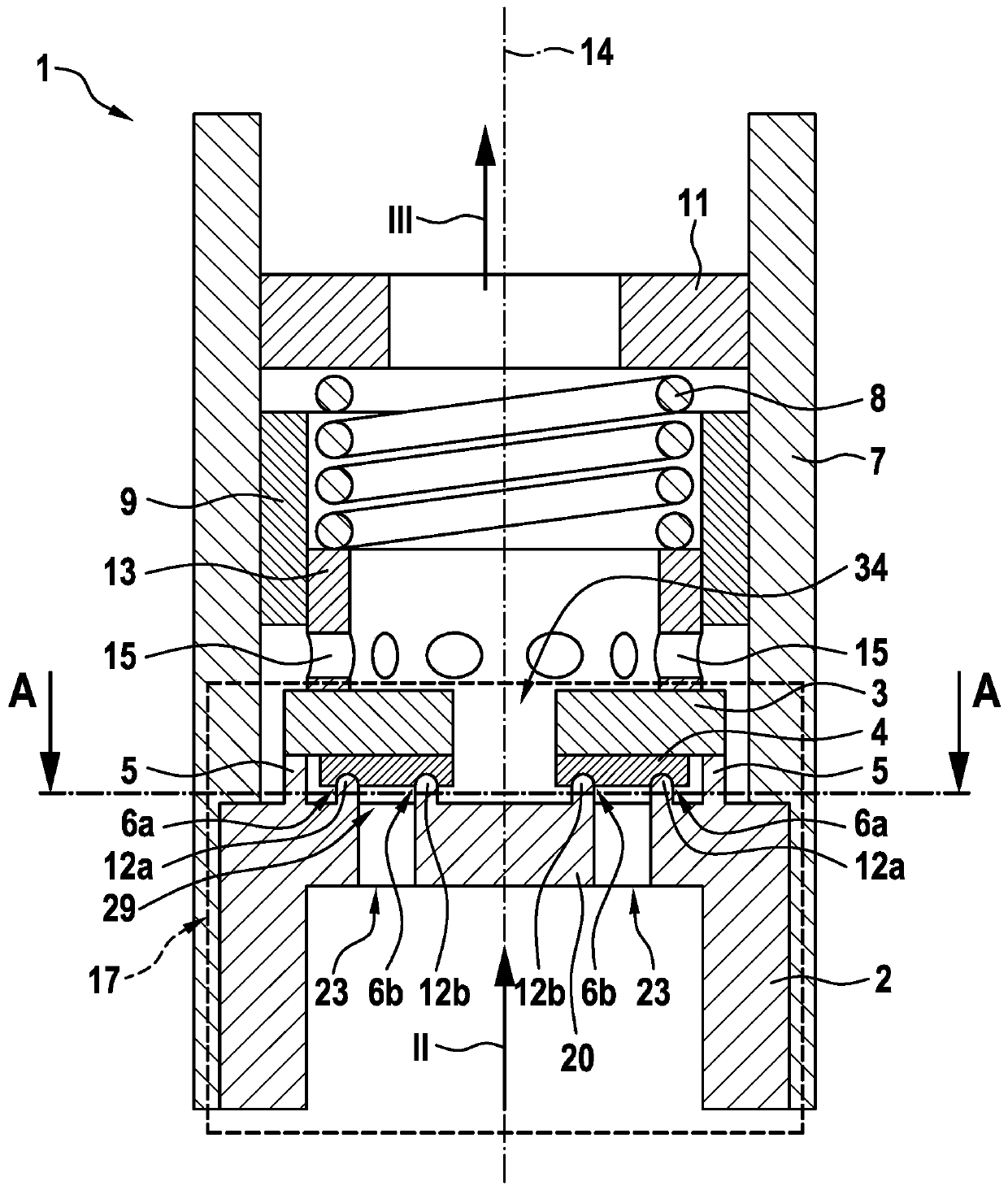
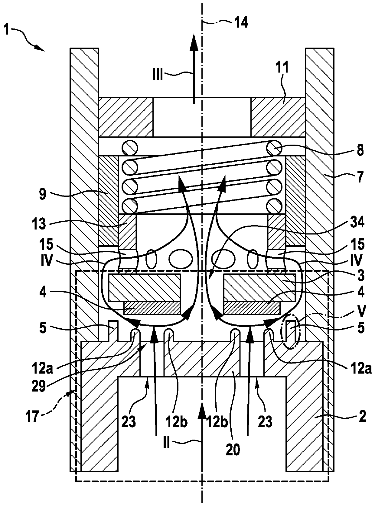
[0030] Below, according to a preferred embodiment refer to figure 1 and figure 2 A schematic sectional view of a pressure limiting valve 1 , in particular a gaseous pressure limiting valve 1 , for controlling and discharging media, in particular gaseous media, is shown. The pressure limiting valve 1 shown here serves to control a medium, in particular gaseous hydrogen, which is supplied to a fuel cell 30 in the vehicle, and to discharge a medium starting from a defined pressure range.

[0031] as by figure 1 It can be seen that the gas pressure limiting valve 1 comprises a housing 7, a valve element mounting assembly 17, a sleeve-shaped element 13 on which the closing spring 8 is supported, in particular a guide element 9 for guiding the closing spring 8 and a closing spring support 11. The valve element mounting 17 also has a sealing seat plate 2 and a valve element 3 , wherein the valve element 3 abuts against the sleeve-shaped element 13 in the direction of the longitud...


PUM


Abstract

The invention relates to a gas pressure limiting valve (1) for controlling a gaseous medium, in particular hydrogen, comprising a housing (7) and a valve element assembly (17). The valve element assembly (17) has a valve element (3) which opens and closes, and is thus movable, in the direction of a longitudinal axis (14), and the valve element assembly (17) has a seal seat plate (2). The seal seatplate (2) has a seal seat edge (12) which encircles the longitudinal axis (14) and which forms a seal seat together with the valve element (3) in the closed state of the valve (1). According to the invention, the seal seat plate (2) is designed so as to have a central region (20) which is connected to the seal seat plate (2) via at least one connection web (29). The seal seat plate (2) forms an annular flow passage (23) which runs in the direction of the longitudinal axis (14), and the seal seat plate (2) or the valve element (3) has at least two circulating seal seat edges (12a, 12b) which form at least two seal seats (6a, 6b) together with the valve element (3) or the seal seat plate (2) in the closed state of the valve (1).

Description

technical field [0001] The invention relates to a pressure limiting valve, in particular a gas pressure limiting valve, for controlling and venting a gaseous medium, especially hydrogen, having a valve element assembly and in particular for use in a vehicle with a fuel cell drive . Background technique [0002] In the field of vehicles, in addition to liquid fuels, gaseous fuels will also play an increasingly important role in the future. In particular, in vehicles with a fuel cell drive, the flow of hydrogen must be controlled. Here, the gas flow is no longer controlled discontinuously as in the case of liquid fuel injection, but the gas is taken from at least one high-pressure tank and conducted via the inflow line of the medium-pressure line system to the injector unit. The injector unit conducts the gas to the fuel cell via the connecting lines of the low-pressure line system. [0003] From DE 10 2013 204 563 A1 a pressure limiting valve is known with a housing and a ...

Claims


Application Information

Patent Timeline
IPC IPC(8): F02M21/02F16K17/04F02M63/00
CPCF16K17/0426F16K17/0466H01M8/04201Y02E60/50
Inventor H-C·马热尔
Owner ROBERT BOSCH GMBH
Why Eureka
Try Eureka