In-situ monitoring device and method for pollution of protective lens for welding laser head

A technology for protecting lenses and monitoring devices, applied in welding equipment, laser welding equipment, metal processing equipment, etc., can solve problems such as the inability to guarantee a normal, stable and continuous welding process, so as to facilitate defect removal and continue welding, and reduce the frequency of removal , Improve the effect of welding

Inactive Publication Date: 2020-02-04
AVIC BEIJING AERONAUTICAL MFG TECH RES INST
View PDF25 Cites 5 Cited by
  • Summary
  • Abstract
  • Description
  • Claims
  • Application Information

AI Technical Summary

Problems solved by technology

[0008] The first aspect of the embodiment of the present invention provides an in-situ monitoring device for the pollution of the protective lens of the welding laser head, including the protective lens, monitoring components, data analysis components and execution terminals, which solves the problem that the existing technology cannot guarantee normal, stable and continuous Difficulties in the welding process, the continuous welding defects caused by the pollution of the protective lens can be found in time, and the continuous welding defects can be minimized

Method used


Image

  • In-situ monitoring device and method for pollution of protective lens for welding laser head
  • In-situ monitoring device and method for pollution of protective lens for welding laser head
  • In-situ monitoring device and method for pollution of protective lens for welding laser head

Examples


Embodiment Construction

[0037] Embodiments of the present invention will be further described in detail below in conjunction with the accompanying drawings and examples. The detailed description and accompanying drawings of the following embodiments are used to illustrate the principles of the present invention, but cannot be used to limit the scope of the present invention, that is, the present invention is not limited to the described embodiments, without departing from the spirit of the present invention Any modification, substitution and improvement of parts, components and connection methods are covered under.

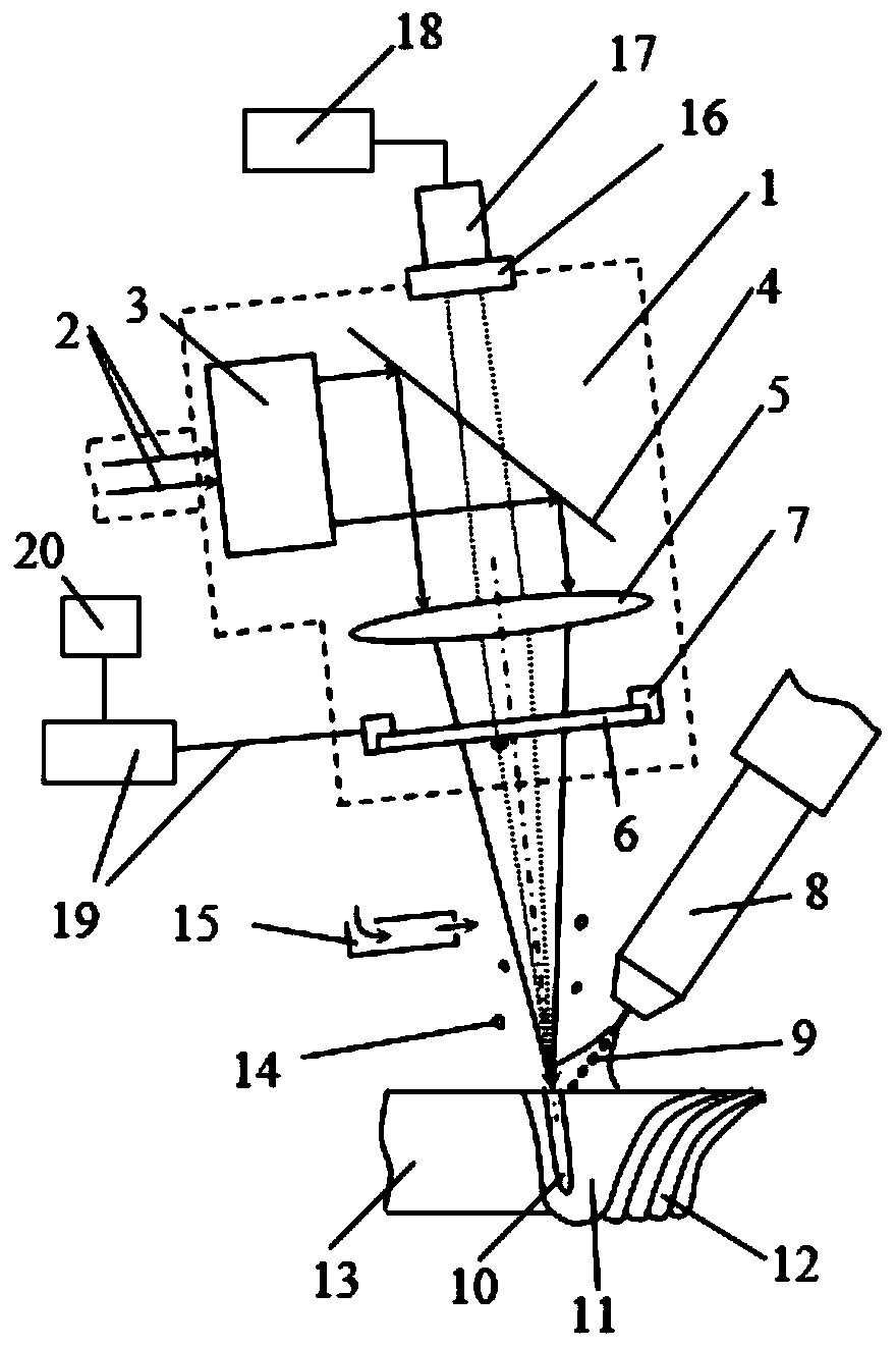
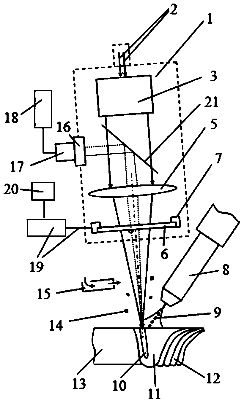
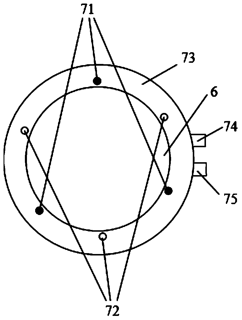
[0038] It should be noted that, in the case of no conflict, the embodiments in the present application and the features in the embodiments can be combined with each other. The following will refer to the attached figure 1 - attached Figure 4 The present application will be described in detail in conjunction with the embodiments.

[0039] First of all, before introducing the in-situ m...


PUM

PropertyMeasurementUnit
diameteraaaaaaaaaa
transmittivityaaaaaaaaaa

Abstract

The invention relates to an in-situ monitoring device and method for pollution of a protective lens for a welding laser head. The in-situ monitoring device comprises the protective lens, a monitoringassembly, a data analysis assembly and an executing terminal; the monitoring assembly is used for monitoring the pollution situation of a laser transmission area on the protective lens; the data analysis assembly is used for calculating the polluted area of the laser transmission area on the protective lens in real time, and the polluted area is compared with a preset threshold value; and when thepolluted area calculated by the data analysis assembly is larger than the preset threshold value, the executing terminal executes a welding interrupt instruction, and the welding laser head stops welding. The welding process of continuous welding defects caused by serious pollution of the protective lens can be stopped in time, subsequent defect elimination and welding continuing are convenient,the obsolescence risk of weldments is lowered to the utmost extent, and the welding pass percentage is further increased.

Description

technical field [0001] The invention relates to the field of welding technology, in particular to an in-situ monitoring device and method for protecting lens contamination of a welding laser head. Background technique [0002] Laser-arc hybrid welding can not only maintain the advantages of low heat input of laser welding, fast welding speed, large weld depth-width ratio, and excellent welding quality, but also overcome the limitation of high precision assembly before welding, so it is a new and efficient welding method. In the laser-arc hybrid welding process, the high-energy-density laser beam, welding holes, molten pool, arc, metal vapor / plasma, and shielding gas maintain complex heat and mass transfer functions. During the above action process, the base metal is rapidly melted and vaporized, and a certain amount of welding spatter is produced. For materials such as aluminum alloys and magnesium alloys, the surface tension in the molten state is small, and the spatter g...

Claims


Application Information

Patent Timeline
Patent Type & Authority Applications(China)
IPC IPC(8): B23K26/70
CPCB23K26/70B23K26/702
Inventor 许飞陈俐邢一思何恩光王瑞欣
Owner AVIC BEIJING AERONAUTICAL MFG TECH RES INST
Why Eureka
Try Eureka