Round rebar feeding device

A feeding device and steel bar technology, applied in the direction of transportation and packaging, conveyors, conveyor objects, etc., can solve the problems that cannot meet the requirements of round bar steel bar transportation, increase labor costs, and limit the use range, etc., to achieve design saving Electricity, high positioning efficiency, convenient post-maintenance effect

Inactive Publication Date: 2020-02-04
CHINA METALLURGICAL CONSTR ENG GRP
View PDF5 Cites 0 Cited by
  • Summary
  • Abstract
  • Description
  • Claims
  • Application Information

AI Technical Summary

Problems solved by technology

Due to the different sizes of round bars required for welding, it is necessary to manually select the matching round bars before welding. After the selection, the single round bars are manually transported to the welding point, which increases the labor cost. , low work efficiency
[0003] In order to solve the above technical problems, after the round bar steel bar is cut into a specified length, the round bar steel

Method used


Image

  • Round rebar feeding device
  • Round rebar feeding device
  • Round rebar feeding device

Examples


Embodiment Construction

[0030] The present invention will be further described below in conjunction with the accompanying drawings and embodiments.

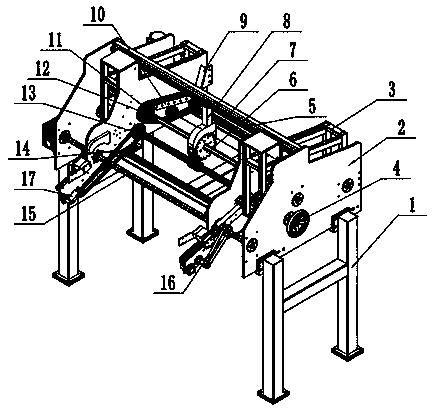
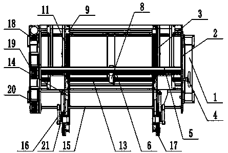
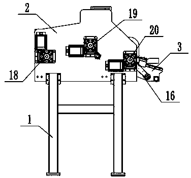
[0031] This example: see Figure 1-Figure 3 , a round bar steel feeding device, including a frame 1, and two corresponding left and right moving frames 3 are arranged on the frame 1, and each moving frame 3 can move left and right on the frame 1, and the moving method can adopt a chute The method is to set a chute on the frame 1 so that the mobile frame 3 can slide left and right along the chute, but it is not limited to this. At the same time, the frame 1 is provided with two corresponding base plates 2, and the mobile frame 3 is located 2, a support rod 5 is provided between the two substrates 2, and the substrate 2 is set to protect the mobile frame 3. The wheel 4 is provided with a first motor 19 , a second motor 20 and a third motor 18 outside the other base plate 2 .

[0032] Simultaneously, in order to drive the mobile frame 2 to move more conv...


PUM


Abstract

The invention discloses a round rebar feeding device. The round rebar feeding device comprises a rack, and two corresponding movable frames capable of moving to adjust the distance between themselvesare arranged on the rack. A vibration part and a quantitative conveying part are arranged on the inner side face of each movable frame in sequence. A first rotary shaft is arranged on the rack, and connected with a first motor arranged on the rack. A ratchet wheel is arranged on the first rotary shaft, and the semicircular outer edge on the ratchet wheel is sleeved with a limiting plate. A conveying channel for clamping and conveying round rebars is formed between the inner side face of the limiting plate and the ratchet wheel. The conveying channel is higher than a first transmission chain, so that when the round rebars are transported in the conveying channel, the first transmission chain and the two ends of each round rebar do not form position interference, the position of the ratchetwheel corresponds to the position of a second transmission chain, and convex sharp protrusions are arranged on the outer surface of the second transmission chain. Storage cavities for conveying the round rebars is formed between the adjacent shape protrusions, the two ends of each round rebar are placed in the storage cavities correspondingly, and a limiting block is arranged at the end, away fromthe ratchet wheel, of the second transmission chain.

Description


Claims


Application Information

Patent Timeline
Owner CHINA METALLURGICAL CONSTR ENG GRP
Why Eureka
Try Eureka