A split conductive ceramic boat

A conductive ceramic, split-type technology, applied in the direction of metal material coating process, vacuum evaporation plating, coating, etc., can solve the problem that metal melting and evaporation stability are greatly affected, affecting large-scale metal evaporation efficiency, conductive ceramic boat Easy to damage and other problems, to avoid changes, maintain stability, and prolong the service life

Active Publication Date: 2021-10-08
山东国晶新材料有限公司
View PDF10 Cites 0 Cited by
  • Summary
  • Abstract
  • Description
  • Claims
  • Application Information

AI Technical Summary

Problems solved by technology

[0002] At present, conductive ceramic boats made of graphite are mostly used in the field of metal thermal evaporation. The conductive ceramic boat itself can be heated to melt and evaporate the metal. This process requires adjustment of the power supply voltage according to the melting and evaporation of the metal. Now the conductive ceramic boat made of graphite Due to the small resistance of the ceramic boat, the adjustment of the power supply voltage has a great influence on the stability of metal melting and evaporation. The conductive ceramic boat is very easy to damage in this process. After the damage, it needs to be reinstalled and adjusted, which greatly affects the efficiency of large-scale metal evaporation. , so it is necessary to find another solution to prolong the life of the conductive ceramic boat and reduce the production cost

Method used


Image

  • A split conductive ceramic boat
  • A split conductive ceramic boat
  • A split conductive ceramic boat

Examples


Embodiment 1

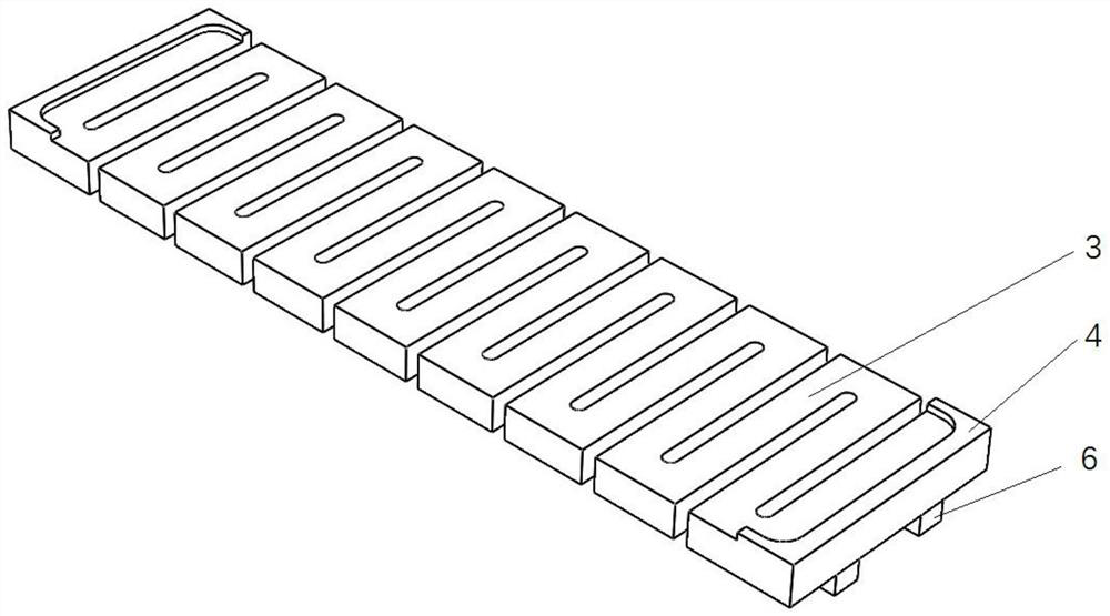
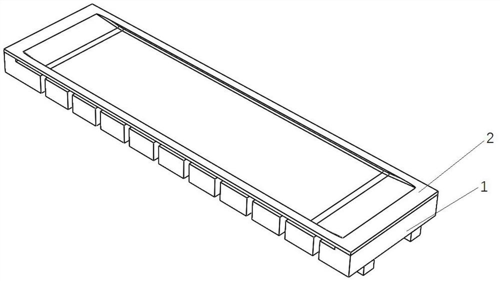
[0026] A split-type conductive ceramic boat, including two parts: a graphite heater and a graphite ceramic boat; the graphite heater is in the shape of a cuboid as a whole, the middle part of the graphite heater is a continuous folded strip, and the top of both ends of the graphite heater are equipped with U-shaped The boss, the U-shaped openings of the two U-shaped bosses are arranged opposite to each other, and the two ends of the graphite heater are connected to the power supply.

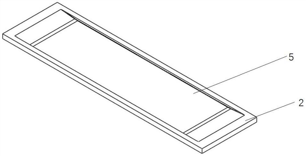
[0027] The graphite ceramic boat is a cuboid plate with a groove on the upper part, which is used to contain molten metal material. The bottom contour of the graphite ceramic boat is consistent with the contours of the two U-shaped bosses of the graphite heater.

[0028] The length of the graphite heater is 200mm, the width is 50mm, and the height is 20mm. Both ends of the heater are connected to the power supply. The heater as a whole contains 20 folded strips. The folded strips are long strips, ...

Embodiment 2

[0036] A split type conductive ceramic boat, its structure is as described in Embodiment 1, the difference is that the U-shaped openings of the two U-shaped bosses are provided with slopes. When the graphite ceramic boat is put in, it is gradually compressed from top to bottom for self-tightening.

Embodiment 3

[0038] A split type conductive ceramic boat, its structure is as described in embodiment 1, the difference is that a graphite material fixing rod is arranged between the two ends of the bottom of the graphite heater, the length of the fixing rod is 200mm, the width is 10mm, and the height is 10mm , with a symmetrical distribution.


PUM

PropertyMeasurementUnit
thicknessaaaaaaaaaa
widthaaaaaaaaaa
heightaaaaaaaaaa

Abstract

The invention relates to a split-type conductive ceramic boat, which belongs to the technical field of metal thermal evaporation. The device includes two parts: a graphite heater and a graphite ceramic boat; There are U-shaped bosses on the top of both ends of the device, and the U-shaped openings of the two U-shaped bosses are set opposite to each other. The two ends of the graphite heater are connected to the power supply; the graphite ceramic boat is a cuboid plate with grooves on the upper part. The groove is used to hold the molten metal material, and the bottom contour of the graphite ceramic boat is consistent with the contours in the two U-shaped bosses of the graphite heater. The heating part of the ceramic boat can be designed separately, and the overall cross-sectional area of ​​the heater circuit becomes smaller, so the resistance of the heating part of the ceramic boat increases, increasing the resistance of the heating part of the ceramic boat, thereby increasing the heating stability of the ceramic boat.

Description

technical field [0001] The invention relates to a split-type conductive ceramic boat body, in particular to a conductive ceramic evaporation boat manufactured by a chemical vapor deposition method, and belongs to the technical field of metal thermal evaporation. Background technique [0002] At present, conductive ceramic boats made of graphite are mostly used in the field of metal thermal evaporation. The conductive ceramic boat itself can be heated to melt and evaporate the metal. This process requires adjustment of the power supply voltage according to the melting and evaporation of the metal. Now the conductive ceramic boat made of graphite Due to the small resistance of the ceramic boat, the adjustment of the power supply voltage has a great influence on the stability of metal melting and evaporation. The conductive ceramic boat is very easy to damage in this process. After the damage, it needs to be reinstalled and adjusted, which greatly affects the efficiency of large...

Claims


Application Information

Patent Timeline
Patent Type & Authority Patents(China)
IPC IPC(8): C23C14/26C23C14/24
CPCC23C14/243C23C14/26
Inventor 刘汝强王殿春孙蕾吴思华赵旭荣
Owner 山东国晶新材料有限公司
Why Eureka
Try Eureka