Building beam column construction pouring construction steel formwork

A steel formwork and beam-column technology, which is applied in the field of building beam-column construction and pouring construction steel formwork, can solve the problems of poor sealing effect of steel formwork, waste of concrete, poor splicing effect, etc., to achieve convenient installation and disassembly, ensure construction efficiency, and seal good effect

Active Publication Date: 2020-02-04
SHENZHEN YUEZHONG GRP
View PDF6 Cites 6 Cited by
  • Summary
  • Abstract
  • Description
  • Claims
  • Application Information

AI Technical Summary

Problems solved by technology

[0005] The present invention can solve the problem that when the existing steel formwork is in use, the splicing effect of the steel formwork is generally poor, installation and disassembly are inconvenient, the steel formwork after splicing is poor in stability, the steel formwork is prone to shaking, and the beams and columns are prone to deformation after pouring , affect the quality of the beams and columns, and in the existing steel formwork pouring process, there are usually gaps between the steel formworks, the sealing effect of the steel formwork is poor, and liquid leakage is prone to occur during the pouring process, resulting in a large amount of waste of concrete, and at the same time , the steel formwork after casting is not easy to remove the formwork, which affects the construction efficiency and other problems

Method used


Image

  • Building beam column construction pouring construction steel formwork
  • Building beam column construction pouring construction steel formwork
  • Building beam column construction pouring construction steel formwork

Examples


Embodiment Construction

[0028] The embodiments of the present invention will be described in detail below with reference to the accompanying drawings, but the present invention can be implemented in a variety of different ways defined and covered by the claims.

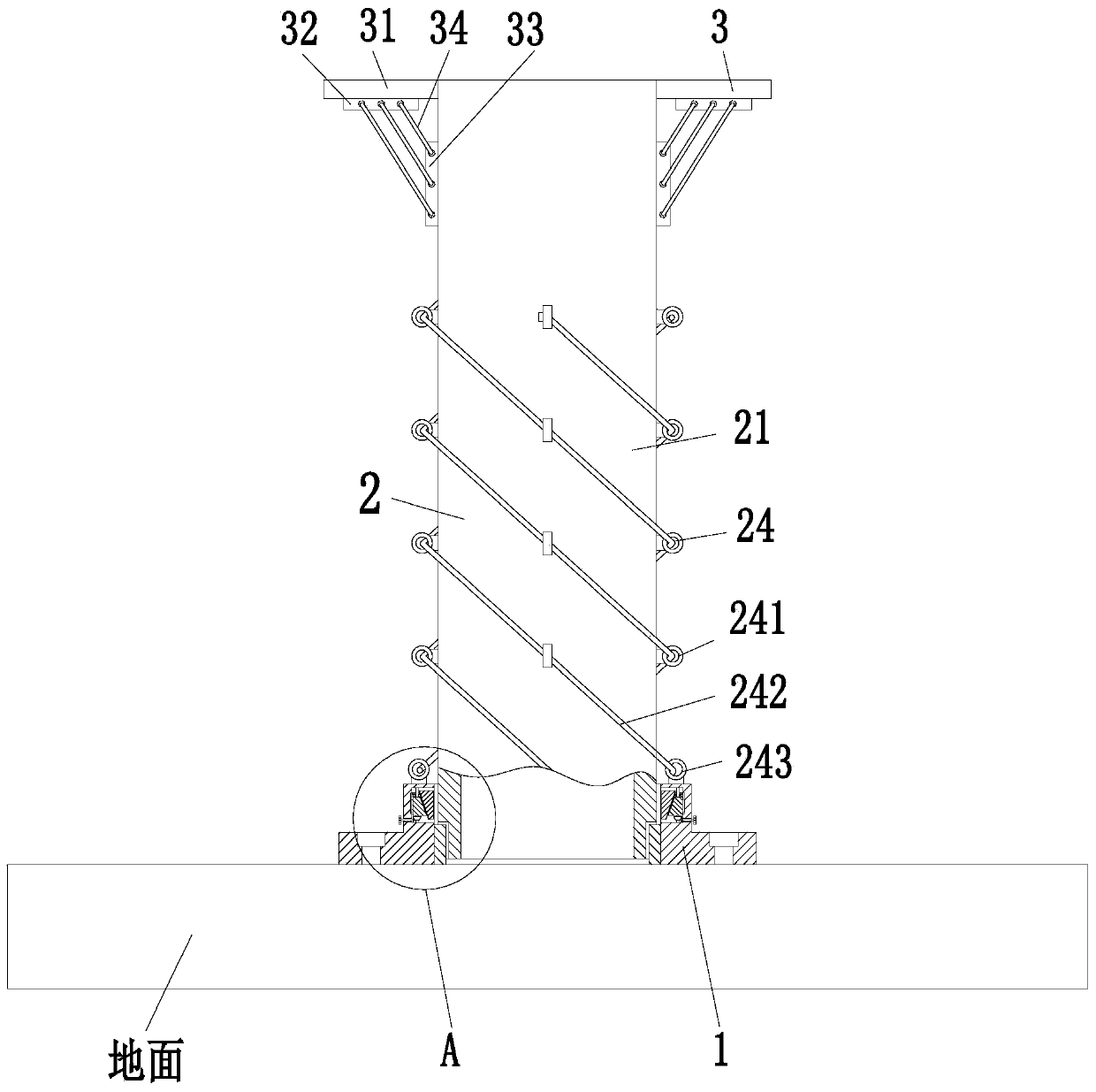
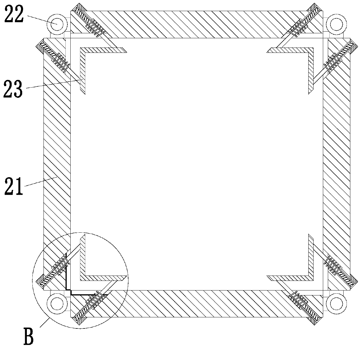
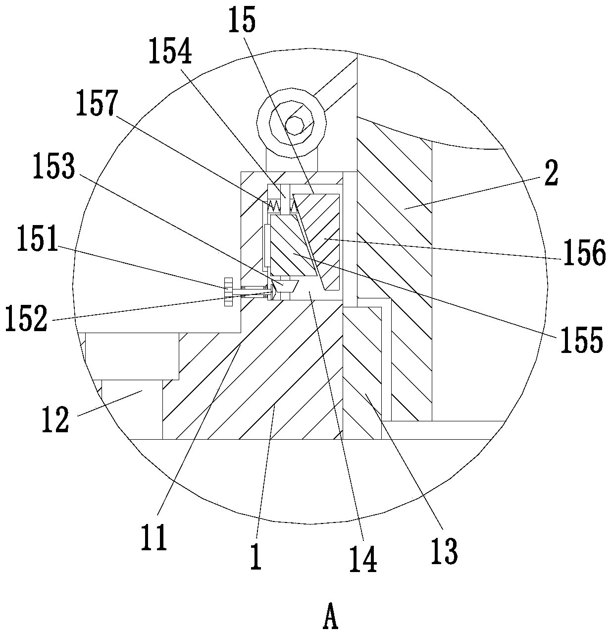
[0029] Such as Figure 1 to Figure 5 As shown, a construction steel formwork for building beams and columns includes a mounting base 1, a steel formwork frame 2 and a support frame 3. The mounting base 1 is installed on the ground, and a steel formwork frame 2 is installed in the middle of the upper end of the mounting base 1. , A support frame 3 is installed at the upper end of the steel formwork frame 2.

[0030] The mounting base 1 includes a mounting frame 11, a mounting hole 12, a clamping plate 13, a concave groove 14 and a clamping mechanism 15. The mounting frame 11 has an L-shaped structure, the number of mounting frames 11 is four, and the mounting frame 11 The splicing is a rectangular structure, the upper end of the mounting frame 11...


PUM


Abstract

The invention relates to a building beam column construction pouring construction steel formwork. The building beam column construction pouring construction steel formwork comprises an installation seat, a steel formwork frame and a support frame, wherein the installation seat is installed on the ground, the steel formwork frame is installed in the middle of the upper end of the installation seat,and the support frame is installed at the upper end of the steel formwork frame. The building beam column construction pouring construction steel template can solve the problems that when the existing steel formwork is used, the conventional splicing effect between the steel formworks is poor, the installation and the disassembly are inconvenient, the stability effect of the spliced steel s is poor, and the steel formworks are easy to shake, so that the poured beam and column are easy to deform and the quality of the beam and column is influenced; in addition, in the pouring process of the existing steel formworks, gaps usually exist between the steel formworks, the sealing effect of the steel formworks is poor, liquid leakage phenomenon is easy to occur in the pouring process, and a large amount of concrete is wasted; meanwhile, the cast formed steel formworks are not easy to dismantle, and the construction efficiency is affected; and the like.

Description

Technical field [0001] The invention relates to the field of pouring steel formwork, in particular to a steel formwork for construction of building beams and columns. Background technique [0002] With the continuous development of the economy, a large number of reinforced concrete buildings have risen from the ground. Precast concrete beams and columns are an important way to speed up the construction progress and improve the construction quality. At present, the popularization of construction projects adopts the cast-in-place reinforced concrete beam and column structure. The process includes erecting, tying steel bars, setting up rigid templates according to the size and shape of beams or columns, forming mold frames, and tightening with hoop, then pouring concrete slurry and tamping, and then removing the mold after the concrete is completely solidified and hardened. [0003] At present, the existing steel formwork for pouring construction usually has the following defects when...

Claims


Application Information

Patent Timeline
Patent Type & Authority Applications(China)
IPC IPC(8): E04G13/02E04G13/04E04G17/00E04G17/04
CPCE04G13/02E04G13/04E04G17/001E04G17/047
Inventor 罗丽芳张纪彬
Owner SHENZHEN YUEZHONG GRP
Why Eureka
Try Eureka