Mechanism capable of realizing forward transmission for two-way driving and reverse transmission for one-way locking

A locking mechanism and two-way drive technology, applied in the field of vehicles, can solve the problems of high cost, difficult research and development, and difficulty in mastering, and achieve the effects of low manufacturing cost and maintenance cost, small space layout difficulty, and small footprint

Pending Publication Date: 2020-02-04
CHONGQING LONGWANG ELECTROMECHANICAL
View PDF0 Cites 1 Cited by
  • Summary
  • Abstract
  • Description
  • Claims
  • Application Information

AI Technical Summary

Problems solved by technology

[0002] When a motor vehicle is parked or started on an uphill road, a downward force parallel to the slope is generated due to the weight of the vehicle itself, that is, the slope resistance, which will cause the vehicle to slide backwards along the slope, which is extremely unsafe
For a manual transmission motor vehicle, the driver must coordinate and cooperate with the parking brake, clutch and accelerator pedal when going uphill, but this series of operations is very cumbersome and difficult to master. It is not easy, and this inherent problem has become a major defect of MT vehicles. At the same time, due to the inherent characteristics of AMT vehicles, it is difficult to control the ramp start of AMT vehicles. This major defect of AMT vehicles hinders the popularization and use of AMT vehicles.
For vehicles equipped with automatic transmission (AT) and continuously variable transmission (CVT), it is also required to have the function of anti-slip slope, adding anti-slope function to the transmission will lead to a more complicated transmission structure and higher cost , and it is difficult to develop

Method used


Image

  • Mechanism capable of realizing forward transmission for two-way driving and reverse transmission for one-way locking
  • Mechanism capable of realizing forward transmission for two-way driving and reverse transmission for one-way locking
  • Mechanism capable of realizing forward transmission for two-way driving and reverse transmission for one-way locking

Examples


Embodiment Construction

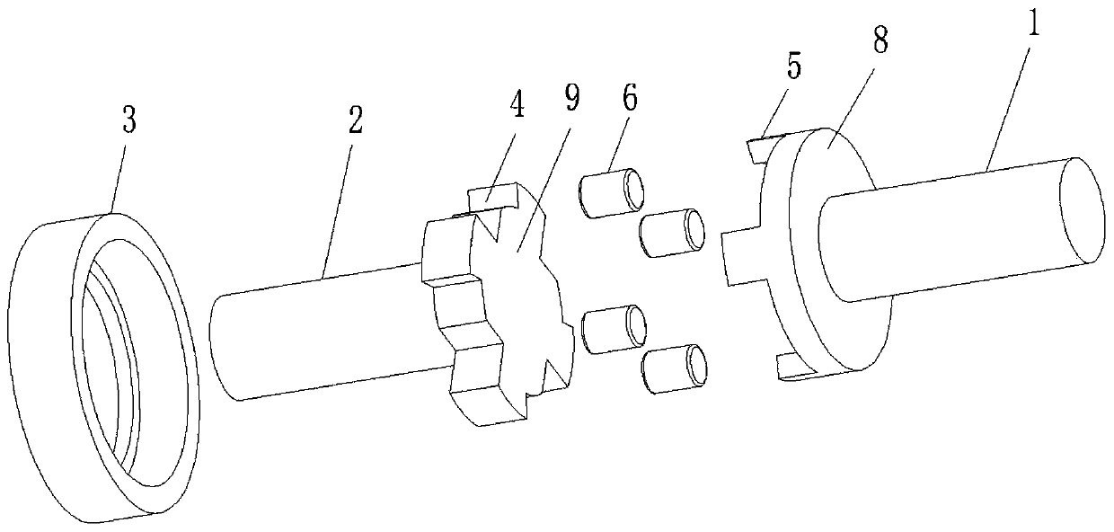
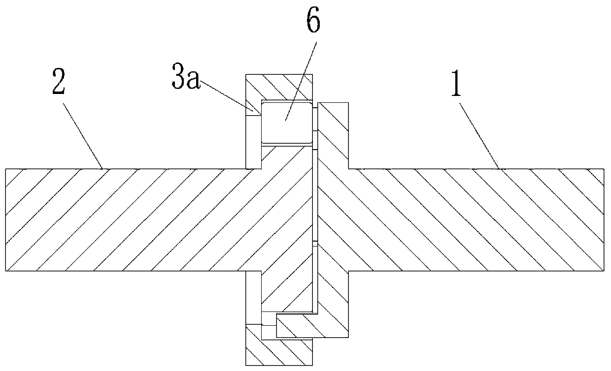
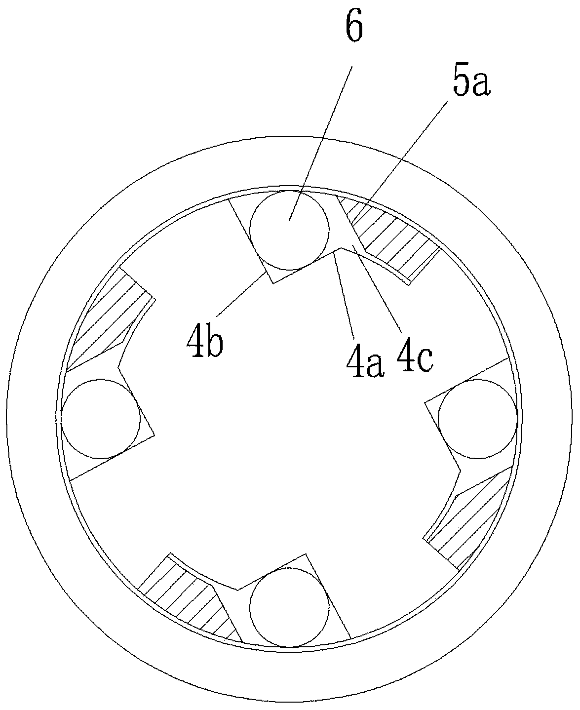
[0027] As shown in the figure, the forward bidirectional drive and reverse unidirectional locking mechanism in this embodiment includes a driving shaft 1, a driven shaft 2 and a fixed housing 3. A locking groove 4 is formed on the end surface of the driven shaft. The end face of the shaft has a coupling tooth 5, the coupling tooth is located in the locking groove to realize the transmission cooperation between the driving shaft and the driven shaft, the fixed housing is sleeved on the joint between the driving shaft and the driven shaft, and a locking mechanism is arranged in the locking groove , the locking mechanism has at least two states of being away from the inner wall of the fixed housing and being pressed against the inner wall of the fixed housing. The driving shaft and the driven shaft are in normal transmission cooperation, and during the inversion process of the driven shaft in reverse transmission, the locking mechanism is pressed against the inner wall of the fixe...


PUM


Abstract

The invention discloses a mechanism capable of realizing forward transmission for two-way driving and reverse transmission for one-way locking. The mechanism comprises a driving shaft, a driven shaftand a fixed shell. Locking grooves are formed in the end face of the driven shaft, engaging teeth are arranged on the end face of the driving shaft, and the engaging teeth are located in the locking grooves. The fixed shell is arranged at the matching position of the driving shaft and the driven shaft in a sleeving mode. Locking mechanisms are arranged in the locking grooves. When the forward-transmission driving shaft rotates reversely and the reverse-transmission driven shaft rotates forwards, the locking mechanisms move away from the inner wall of the fixed shell, so that the driving shaftis in normal transmission fit with the driven shaft. When the reverse-transmission driven shaft rotates reversely, the locking mechanisms are pressed on the inner wall of the fixed shell, so that thedriven shaft is clamped on the fixed shell. According to the mechanism capable of realizing forward transmission for two-way driving and reverse transmission for one-way locking, the function of forward transmission for two-way driving and reverse transmission for one-way locking is realized through the improvement of the matching position of the driving shaft and the driven shaft; and the cost islow, the structure is compact, the occupied space is small, and spatial layout difficulty is low.

Description

technical field [0001] The invention relates to the technical field of vehicles, in particular to a forward drive bidirectional drive and reverse drive one-way locking mechanism. Background technique [0002] When a motor vehicle is parked or started on an uphill road, a downward force parallel to the slope is generated due to the vehicle's own weight, that is, the slope resistance, which will cause the vehicle to slide backward along the slope, which is extremely unsafe. For a manual transmission motor vehicle, the driver must coordinate and cooperate with the parking brake, clutch and accelerator pedal when going uphill, but this series of operations is very cumbersome and difficult to master. It is not easy, and this inherent problem has become a major defect of MT vehicles. At the same time, due to the inherent characteristics of AMT vehicles, it is difficult to control the ramp start of AMT vehicles. This major defect of AMT vehicles hinders the popularization and use o...

Claims


Application Information

Patent Timeline
Patent Type & Authority Applications(China)
IPC IPC(8): F16D41/066
CPCF16D41/066
Inventor 王吉龙罗裕源
Owner CHONGQING LONGWANG ELECTROMECHANICAL
Why Eureka
Try Eureka