A sealing device suitable for corrosive liquids
A sealing device and corrosive technology, applied in the field of sealing device for corrosive liquid and sealing device for filling liquid, can solve the problem of difficult to achieve long-term sealing effect, poor elasticity of polytetrafluoroethylene, sticking between polytetrafluoroethylene and metal shell. In order to meet the sealing requirements, realize the sealing effect, and meet the corrosion resistance requirements
- Summary
- Abstract
- Description
- Claims
- Application Information
AI Technical Summary
Problems solved by technology
Method used
Image
Examples
Embodiment 1
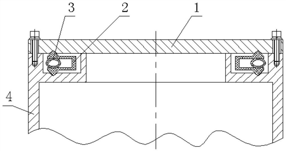
[0047] Such as figure 1 As shown, this embodiment provides a sealing device suitable for corrosive liquids, including an upper part 1, which is characterized in that it also includes a sealing element 2, an annular spring 3, and a lower part 4;
[0048] The upper part 1 is the first circular plate, the first circular plate of the upper part 1 is a body of revolution, the lower surface of the first circular plate of the upper part 1 is the first circular plane, and the first circular plane of the upper part 1 has a circle of the first circular plane. An annular groove, the shaft section of the first annular groove of the upper part 1 is an inverted V shape, and the rotation axis of the first annular groove of the upper part 1 coincides with the axis of the rotary body of the upper part 1;
[0049] The upper part 1 is the upper part of the mechanical connection interface in the liquid-phase charge shell, and the liquid-phase charge is located at the lower end of the upper part 1...
Embodiment 2
[0092] Such as figure 1 As shown, this embodiment provides a sealing device suitable for corrosive liquids, including an upper part 1, which is characterized in that it also includes a sealing element 2, an annular spring 3, and a lower part 4;
[0093] The upper part 1 is the first circular plate, the first circular plate of the upper part 1 is a body of revolution, the lower surface of the first circular plate of the upper part 1 is the first circular plane, and the first circular plane of the upper part 1 has a circle of the first circular plane. An annular groove, the shaft section of the first annular groove of the upper part 1 is an inverted V shape, and the rotation axis of the first annular groove of the upper part 1 coincides with the axis of the rotary body of the upper part 1;
[0094] The upper part 1 is the upper part of the mechanical connection interface in the liquid-phase charge shell, and the liquid-phase charge is located at the lower end of the upper part 1...
Embodiment 3
[0137] Such as figure 1 As shown, this embodiment provides a sealing device suitable for corrosive liquids, including an upper part 1, which is characterized in that it also includes a sealing element 2, an annular spring 3, and a lower part 4;
[0138] The upper part 1 is the first circular plate, the first circular plate of the upper part 1 is a body of revolution, the lower surface of the first circular plate of the upper part 1 is the first circular plane, and the first circular plane of the upper part 1 has a circle of the first circular plane. An annular groove, the shaft section of the first annular groove of the upper part 1 is an inverted V shape, and the rotation axis of the first annular groove of the upper part 1 coincides with the axis of the rotary body of the upper part 1;
[0139] The upper part 1 is the upper part of the mechanical connection interface in the liquid-phase charge shell, and the liquid-phase charge is located at the lower end of the upper part 1...
PUM
 Abstract
Description
Claims
Application Information
 - R&D
- Intellectual Property
- Life Sciences
- Materials
- Tech Scout
- Unparalleled Data Quality
- Higher Quality Content
- 60% Fewer Hallucinations
Browse by: Latest US Patents, China's latest patents, Technical Efficacy Thesaurus, Application Domain, Technology Topic, Popular Technical Reports.
© 2025 PatSnap. All rights reserved.Legal|Privacy policy|Modern Slavery Act Transparency Statement|Sitemap|About US| Contact US: help@patsnap.com

