
Singularized spherical-element conveying device applied to high-temperature gas cooled reactor

A high-temperature gas-cooled reactor and spherical element technology, which is applied in the field of reactor engineering to achieve the effects of easy replacement and maintenance and precise control of the rotor angle

Active Publication Date: 2012-11-14
CHINERGY CO LTD
View PDF1 Cites 0 Cited by
  • Summary
  • Abstract
  • Description
  • Claims
  • Application Information

AI Technical Summary

Problems solved by technology

[0007] The technical problems to be solved by the present invention are: (1) How to provide a single delivery device for spherical components used in the high temperature gas-cooled reactor fuel loading and unloading system, so as to ensure the physical integrity of the delivery components, and be applicable to applications requiring frequent start and stop , fast and stable, precise control, long service life, and convenient maintenance working environment; (2) For the single delivery device on the pressure pipeline connected to the pressure boundary of the primary circuit of the reactor, how to seal the medium-temperature and medium-pressure helium atmosphere in the pipeline system , how to prevent the leakage of radioactive atmosphere, and how to ensure a suitable operating environment for equipment components; (3) for the single conveying device upstream of the pneumatic conveying pipeline for spherical elements, how to block the airflow in the flow pipe section of the spherical element due to its own weight, and how to make the load in the pipeline How to ensure the reliability of pneumatic conveying of spherical elements with one-way flow of gas

Method used


Image

  • Singularized spherical-element conveying device applied to high-temperature gas cooled reactor
  • Singularized spherical-element conveying device applied to high-temperature gas cooled reactor
  • Singularized spherical-element conveying device applied to high-temperature gas cooled reactor

Examples


Embodiment Construction

[0055] In order to make the purpose, content, and advantages of the present invention clearer, the specific implementation manners of the present invention will be further described in detail below in conjunction with the accompanying drawings and embodiments.

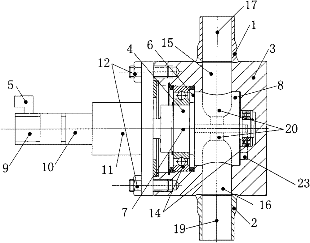
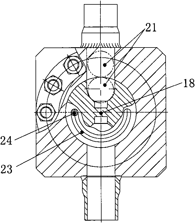
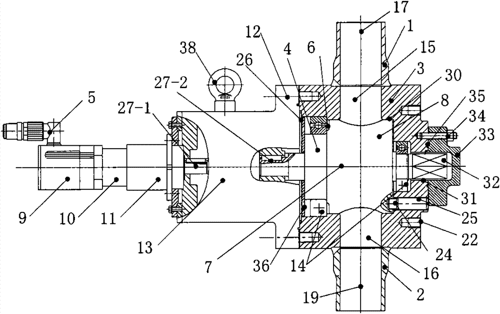
[0056] Such as Picture 1-1 with Figure 1-2 as shown, Picture 1-1 with Figure 1-2 It shows the basic structure of the high-temperature gas-cooled reactor spherical element pipeline simplification delivery device involved in the present invention.

[0057] Wherein, the working chamber of box body 3 comprises a cylindrical counterbore 6, and rotor 4 is supported in the cylindrical counterbore 6 of box body 3 through bearing 14, and the corresponding working section on the rotor 4 is round platform 8, and round platform 8 and cylinder The counterbores 6 have the same first axis 7 .

[0058] The drive part 5 includes an AC servo motor 9 and a planetary gear reducer 10 directly connected with it, and both the motor 9 a...


PUM


Abstract

The invention relates to a singularized spherical-element conveying device applied to a high-temperature gas cooled reactor, belonging to the technical field of reactor engineering. The singularized spherical-element conveying device comprises a sphere inlet pipe, a sphere outlet pipe, a box body, a rotor and a driving part; the box body comprises a sphere inlet channel and a sphere outlet channel, and the sphere inlet pipe and the sphere outlet channel as well as the sphere outlet pipe and the sphere outlet channel are both coaxially welded; the box body comprises a cylindrical counter bore,and the rotor is supported in the cylindrical counter bore through a bearing and comprises a sphere receiving cup; the driving part comprises a motor and a speed reducer, is connected with the box body through a support and a fastener, and drives the rotor to rotate through a coupler; and the axes of the sphere inlet channel, the sphere outlet channel and the sphere receiving cup are positioned on the same plane and vertical to the axis of the cylindrical counter bore, and all the axes are intersected in one point. The singularized spherical-element conveying device provided by the invention can be started and stopped frequently, be used for performing a singularized spherical-element conveying function rapidly, stably and accurately, and meet the running requirements for entity integrityof conveyed elements, and has the characteristics of long service life, easiness for maintenance and reliability.

Description

technical field [0001] The invention belongs to the technical field of reactor engineering, and in particular relates to a spherical element unitary conveying device used in a high-temperature gas-cooled reactor fuel loading and unloading system through a ball pipeline. Background technique [0002] The pebble bed high-temperature gas-cooled reactor uses spherical elements to pass through the core multiple times to achieve non-stop continuous operation. On the HTR-10 MW high-temperature gas-cooled experimental reactor, 125 fuel spheres participate in the circulation every day, and 25 new fuels are loaded and 25 spent fuels are discharged. Due to the low circulation and loading and unloading speed, by controlling the rotating speed of the broken ball separator spiral roller and dynamically cooperating with the operation of the lifter, it can fully meet the needs of single core unloading, core fuel ball burnup measurement, main circulation fuel ball lifting and depletion. Sim...

Claims


Application Information

Patent Timeline
Patent Type & Authority Patents(China)
IPC IPC(8): G21C19/20
CPCY02E30/30
Inventor 张海泉李红克王鑫聂君锋刘继国吴宗鑫张作义
Owner CHINERGY CO LTD
Learn More