
Method for preparing optical cables of optical fiber grating array for positioning and speed measurement of high-speed magnetic levitation train

A fiber grating array, magnetic levitation train technology, which is applied to devices using optical methods, cladding fibers, grating fibers, etc., can solve the problems of weak anti-interference ability, complex equipment design, low precision, etc., and achieve strong anti-electromagnetic interference ability. , The effect of reasonable design structure and high measurement accuracy

Active Publication Date: 2020-02-04
WUHAN UNIV OF TECH
View PDF8 Cites 2 Cited by
  • Summary
  • Abstract
  • Description
  • Claims
  • Application Information

AI Technical Summary

Problems solved by technology

However, the difficulty in realizing this method lies in the high precision requirements of each device in the train position detection system, which leads to complex equipment design, high manufacturing, installation and later maintenance costs.
Germany's high-speed maglev railway adopts the method of "combining beacon and pole distance detection" for the positioning and speed measurement of the train. In some cases, the train running position obtained can only indicate that the train is between two adjacent beacons, and its reliability and accuracy still cannot guarantee the absolute safety of the train running
[0005] At present, electric sensors are widely used in my country to realize the speed measurement and positioning of trains. However, traditional electric sensors have poor reliability, low precision, and weak anti-interference ability.
Especially in today's development of high-speed railway electrification, in the face of strong electromagnetic interference, harsh environment and abnormal weather, electrical sensors often make misjudgments

Method used


Image

  • Method for preparing optical cables of optical fiber grating array for positioning and speed measurement of high-speed magnetic levitation train
  • Method for preparing optical cables of optical fiber grating array for positioning and speed measurement of high-speed magnetic levitation train

Examples


Embodiment Construction

[0031] The technical solutions of the present invention will be described below in conjunction with the accompanying drawings and embodiments.

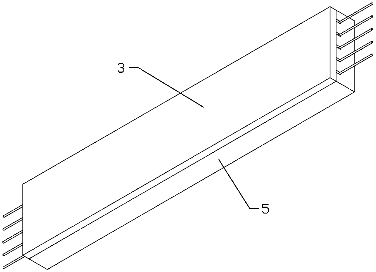
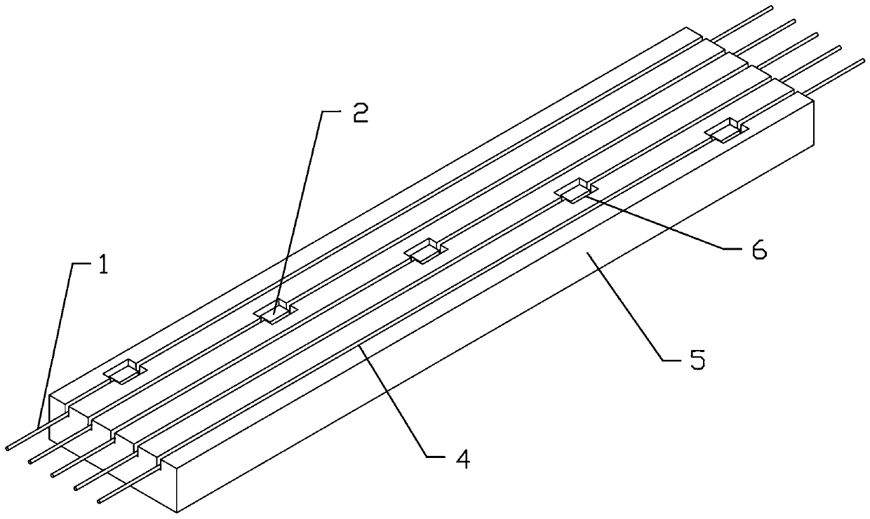
[0032] Such as figure 1 with figure 2 As shown, a method for preparing a fiber grating array optical cable used in the long-distance positioning and speed measurement system of a high-speed maglev train according to the present invention requires the following equipment and materials in the preparation process: an automatic glue dispenser with ultraviolet curing function, glue dispenser Loading platform, tension loading mechanism, linear material automatic retracting and unwinding equipment, stirring device, automatic cable forming equipment, ultraviolet curing glue, magnetic powder, flat polymer bottom belt 5, flat polymer flexible top belt 3, and fiber grating array 1,

[0033] Its preparation method comprises the following steps:

[0034] Step 1): Write the grating array 1 continuously in the same optical fiber. The length of th...


PUM

PropertyMeasurementUnit
Lengthaaaaaaaaaa
Granularityaaaaaaaaaa
Lengthaaaaaaaaaa

Abstract

The invention relates to the technical field of optical fiber sensing, in particular to a method for preparing optical cables of an optical fiber grating array for a long-distance positioning and speed measurement system for a high-speed magnetic levitation train. Equipment and materials requiring to be adopted in the preparation process of the optical cables are as follows: an automatic dispensing machine with an ultraviolet curing function, a dispensing loading platform, a tension loading mechanism, linear material automatic retracting and releasing equipment, a stirring device, automatic cabling equipment, an ultraviolet curing adhesive, magnetic powder, a flat polymer bottom band, a flat polymer flexible top band and the optical fiber grating array. The center of each low-reflectivityshort grating is coated with the corresponding magnetic powder to achieve strain sensing of magnetic materials, and by combining a plurality of sets of grating strain sensing arrays, each single optical cable can achieve 1 cm of positioning resolution and related speed measurement within the 10-km distance.

Description

technical field [0001] The invention relates to the technical field of optical fiber sensing, in particular to a method for preparing an optical fiber grating array optical cable used in a long-distance positioning and speed measuring system of a high-speed maglev train. Background technique [0002] Rail transit is the lifeblood of my country's national economy and the backbone network of the comprehensive transportation system. It not only undertakes the transportation of most national strategies and economic materials, but also undertakes the function of passenger transportation. It plays a role in promoting my country's resource transportation, strengthening regional economic exchanges, It has played a huge role in solving urban traffic congestion. With the rapid development of high-speed railways and urban subways and the high-speed and intensive rail transit operations, their safety issues have become a major challenge that affects and restricts the construction and dev...

Claims


Application Information

Patent Timeline
IPC IPC(8): G02B6/02G02B6/44G01P3/36G01B11/00
CPCG01B11/00G01P3/36G02B6/02057G02B6/02123G02B6/4479
Inventor 童杏林魏敬闯邓承伟张翠许欧阳冒燕
Owner WUHAN UNIV OF TECH
Learn More