Rotor iron core piece, rotor iron core, rotor, permanent magnet synchronous motor and related products

A rotor core and rotor iron technology, applied to synchronous motors with stationary armatures and rotating magnets, motors, magnetic circuits, etc., can solve the problems of increased cost and large amount of permanent magnets

Pending Publication Date: 2020-02-04
HUAWEI DIGITAL POWER TECH CO LTD
View PDF6 Cites 7 Cited by
  • Summary
  • Abstract
  • Description
  • Claims
  • Application Information

AI Technical Summary

Problems solved by technology

In order to output the set motor torque to meet the demand, it is necessary to increase the proportion

Method used


Image

  • Rotor iron core piece, rotor iron core, rotor, permanent magnet synchronous motor and related products
  • Rotor iron core piece, rotor iron core, rotor, permanent magnet synchronous motor and related products
  • Rotor iron core piece, rotor iron core, rotor, permanent magnet synchronous motor and related products

Examples


Embodiment Construction

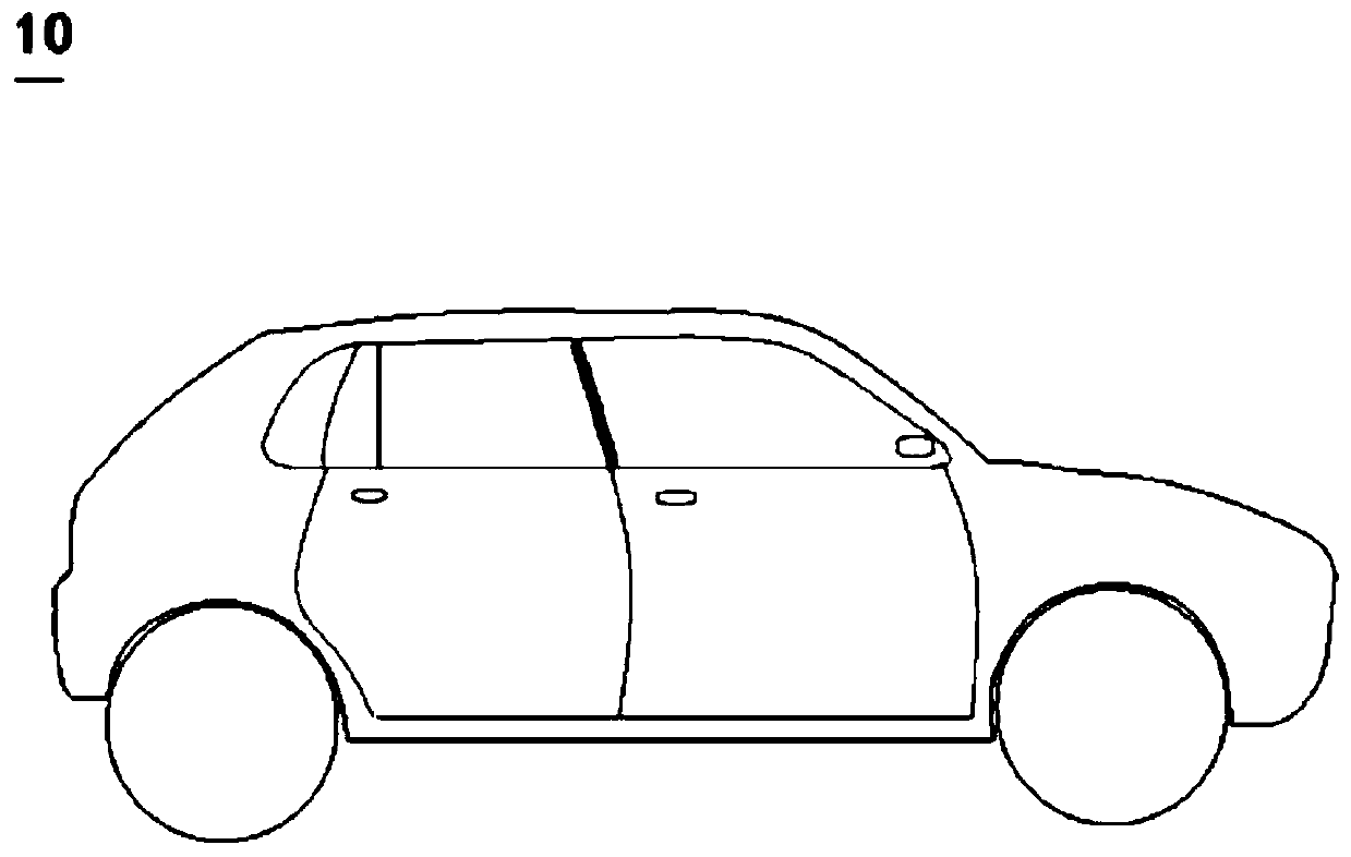
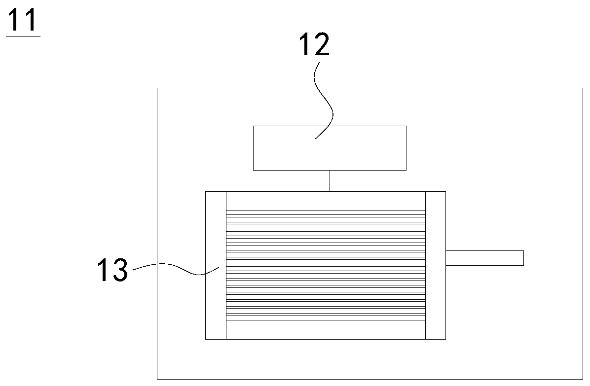
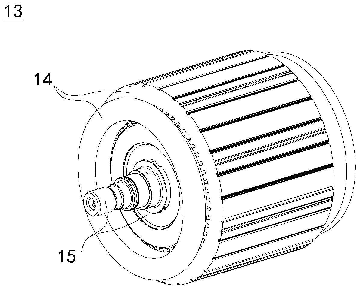
[0038] The embodiment of this application provides an electric vehicle, including but not limited to electric cars, electric buses, electric motorcycles, etc., for example figure 1 An electric SUV (Sport Utility Vehicle, sport utility vehicle) 10 is schematically shown. The electric vehicle 10 may include a frame and a powertrain mounted on the frame. Among them, the vehicle frame serves as the structural skeleton of the electric vehicle 10, and is used to support, fix and connect various assemblies, and bear loads from the interior of the vehicle system and from the external environment. A powertrain is a system of components used to generate and transmit power to the road. Such as figure 2 As shown, the powertrain 11 may include a motor controller 12 and a permanent magnet synchronous motor 13 . The motor controller 12 is electrically connected with the permanent magnet synchronous motor 13 and used for controlling the operation of the permanent magnet synchronous motor ...


PUM


Abstract

The application provides a rotor structure of a permanent magnet synchronous motor applied to an electric vehicle. The rotor structure uses a built-in double-layer V-shaped magnetic pole structure. Amagnetic pole included angle of an inner-layer V-shaped magnetic pole structure is larger than a magnetic pole included angle of an outer-layer V-shaped magnetic pole structure, and a difference valueof the two parts is within [0 degrees, 50 degrees]. Width of a permanent magnet slot of the inner-layer magnetic pole structure is 1.5-2 times of width of a permanent magnet slot of the outer-layer magnetic pole structure. The application also provides the permanent magnet synchronous motor including the rotor structure, a power assembly including the permanent magnet synchronous motor, and the electric vehicle including the power assembly. Through reasonable numerical matching on the magnetic pole included angle of the inner and outer magnetic pole structures and the width of the permanent magnet slots, the scheme of the application can increase a saliency ratio of the permanent magnet synchronous motor, reduce the amount of permanent magnet use, and reduce cost.

Description

technical field [0001] The present application relates to the technical field of electric vehicles, in particular to a rotor core, a rotor core, a rotor, a permanent magnet synchronous motor, a power assembly and an electric vehicle. Background technique [0002] Built-in permanent magnet synchronous motors are widely used in electric vehicle powertrain systems. The rotor of the built-in permanent magnet synchronous motor includes a rotor iron core and a permanent magnet. A magnetic groove is opened in the rotor iron core, and the permanent magnet is installed in the magnetic groove. [0003] The motor torque of a permanent magnet synchronous motor is equal to the sum of the permanent magnet torque and the reluctance torque. The traditional interior permanent magnet synchronous motor has limited saliency ratio, which makes the motor's utilization rate of reluctance torque low. In order to output the set motor torque to meet the demand, it is necessary to increase the propo...

Claims


Application Information

Patent Timeline
IPC IPC(8): H02K1/27H02K21/14
CPCH02K1/2773H02K21/14H02K2213/03H02K2201/03Y02T10/64H02K1/2766
Inventor 李义额尔和木巴亚尔李孟德
Owner HUAWEI DIGITAL POWER TECH CO LTD
Why Eureka
Try Eureka