Collaborative robot modularized joint compact in structure

A technology of modular joints and compact structure, which is applied in the direction of manipulators, program-controlled manipulators, manufacturing tools, etc. It can solve the problems of low joint integration, poor modularization, and long design cycle, so as to achieve compact joint structure and increase design flexibility. , The effect of saving axial space

Pending Publication Date: 2020-02-07
敬科(深圳)机器人科技有限公司
View PDF0 Cites 8 Cited by
  • Summary
  • Abstract
  • Description
  • Claims
  • Application Information

AI Technical Summary

Problems solved by technology

[0006] Purpose of the invention: The purpose of the present invention is to overcome the disadvantages of the prior art and design a modular joint of a collaborative robot with a compact structure. question

Method used


Image

  • Collaborative robot modularized joint compact in structure
  • Collaborative robot modularized joint compact in structure
  • Collaborative robot modularized joint compact in structure

Examples


specific Embodiment approach 1

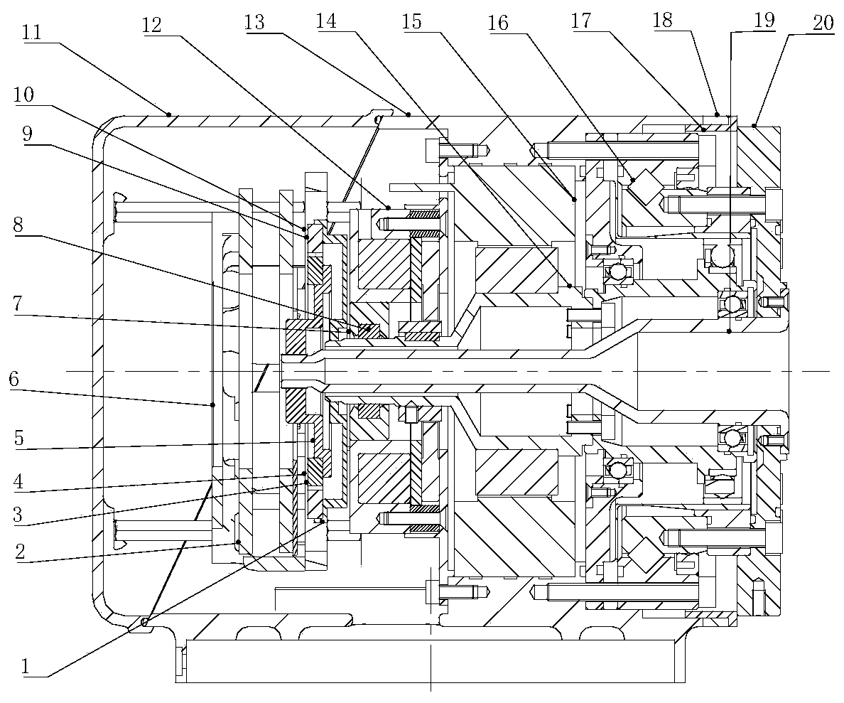
[0048] Embodiment 1: it includes a joint casing, a drive mechanism, a motor assembly and an output mechanism; the drive mechanism, the motor assembly 15 and the output mechanism are sequentially arranged inside the joint casing, the input end of the motor assembly is connected to the drive mechanism, and the motor assembly 15 The output terminal is connected with the output mechanism.

specific Embodiment approach 2

[0050] The drive mechanism includes a motor end encoder code disc mounting seat 1, a joint servo driver 2, a joint end encoder code disc 3, a joint end encoder reading head 4, a joint end encoder code disc mounting seat 5, a driver bracket 6, Encoder code disc 9 at the motor end, encoder reading head 10 at the motor end, brake assembly 12;

[0051] The motor assembly 15 includes a motor stator, an internal motor rotor and a motor shaft 14;

[0052] The output mechanism includes a harmonic reducer 16, a low-speed wire protection tube 19 and an output flange;

[0053] The joint casing includes a joint housing 13 and a joint rear cover 11;

[0054] The driver bracket 6, the encoder code disc mount 5 at the joint end, the encoder code disc mount 1 at the motor end, the brake assembly 12, the motor assembly 15 and the harmonic reducer 16 are sequentially fixed on the joint housing 13;

[0055] The driver bracket 6 is fixedly connected to the joint housing 13, the joint servo driver...

specific Embodiment approach 3

[0064] Embodiment 3: The inner ring of the brake assembly 12 is provided with a sealing ring mounting seat 7 , and the sealing ring mounting seat 7 is provided with a sealing ring one 8 , and the inner ring of the sealing ring one 8 is in contact with the motor shaft 14 .

[0065] Other implementation manners are the same as the second embodiment.


PUM


Abstract

The invention discloses a collaborative robot modularized joint compact in structure. The modularized joint is composed of a joint shell, a joint output flange, a low-speed wire protection pipe, a harmonic reducer, a motor assembly, a motor shaft, a brake assembly, a motor end encoder assembly and a joint end encoder assembly which are sequentially connected. The low-speed wire protection pipe isconnected with the joint output flange. The harmonic reducer is connected with the joint output flange and the joint shell. The motor assembly comprises a stator and a rotor. The motor shaft is connected with the motor rotor. One end of the motor shaft is connected with the input end of the harmonic reducer. The brake assembly is of a magnetic attraction friction type, capable of achieving lockingwhen powered off, capable of achieving unlocking when powered on and connected to the motor shaft. Compared with a plug pin type brake, sudden stop is safe, and stop pins cannot be bent. A motor endencoder coded disc and a joint end encoder coded disc are concentrically arranged. A motor end encoder reading head and a joint end encoder reading head are integrated together, the axial space of thejoint can be compact, the integration level can be high, the wiring space is large, and operation is facilitated; and meanwhile the modularized joint further has the characteristics of being high inrigidity and large in load-dead weight ratio.

Description

technical field [0001] The invention relates to the technical field of robot joints, in particular to a collaborative robot modular joint, in particular to a compact collaborative robot modular joint. Background technique [0002] In the context of German Industry 4.0, the country has introduced the "Made in China 2025" plan, which puts forward requirements for high-end intelligent equipment, and the intelligent robot industry has ushered in a new round of development opportunities; The transformation of production to user customization has a strong demand for flexible, intelligent and personalized manufacturing; as an important branch of robots, collaborative robots have achieved rapid development since their birth, the industrialization process has been accelerating, and new manufacturers have continued to increase. The fields of application continue to expand, and the business model continues to innovate. [0003] Human-machine collaborative robots have outstanding advan...

Claims


Application Information

Patent Timeline
Patent Type & Authority Applications(China)
IPC IPC(8): B25J17/00B25J9/08
CPCB25J9/08B25J17/00
Inventor 郭廷山孙敬颋陈杰
Owner 敬科(深圳)机器人科技有限公司
Why Eureka
Try Eureka