Injection device of electric injection molding machine

An injection device and injection molding machine technology, applied in the field of injection molding machine injection devices, can solve problems such as unfavorable assembly of injection units and different bodies, insufficient use of injection stroke length, affecting injection acceleration and response time, etc., to improve space utilization, Compact, mass-reduced effect

Inactive Publication Date: 2020-02-07
宁波力劲塑机智造有限公司
View PDF5 Cites 2 Cited by
  • Summary
  • Abstract
  • Description
  • Claims
  • Application Information

AI Technical Summary

Problems solved by technology

In the existing injection device of electric injection molding machine, the injection screw only rotates but does not move, and the injection driven wheel is fixed on the injection screw. This arrangement will cause the length of the injection stroke to not be fully utilized, resulting in an increase in the axial length of the injection unit. It is not conducive to the assembly of the injection unit and different bodies. At the same time, since the pre-molding unit is installed on the injection rod, the injection motor needs to drive the pre-molding unit during the injection operation. The pre-molding unit is composed of the entire pre-molding base and the pre-molding motor. , has a large weight, which will greatly affect the injection acceleration and response time, and will also reduce the accuracy and stability of the injection rod, affecting the key performance of the equipment. In order to solve the above problems, it is necessary to design a new injection device of

Method used


Image

  • Injection device of electric injection molding machine
  • Injection device of electric injection molding machine
  • Injection device of electric injection molding machine

Examples


Embodiment Construction

[0024] Below in conjunction with specific embodiment, further illustrate the present invention. It should be understood that these examples are only used to illustrate the present invention and are not intended to limit the scope of the present invention. In addition, it should be understood that after reading the teachings of the present invention, those skilled in the art can make various changes or modifications to the present invention, and these equivalent forms also fall within the scope defined by the appended claims of the present application.

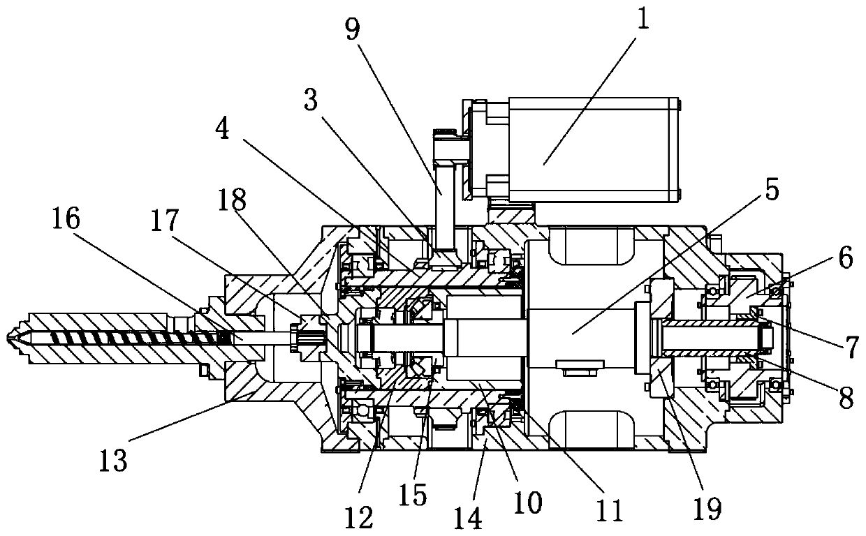
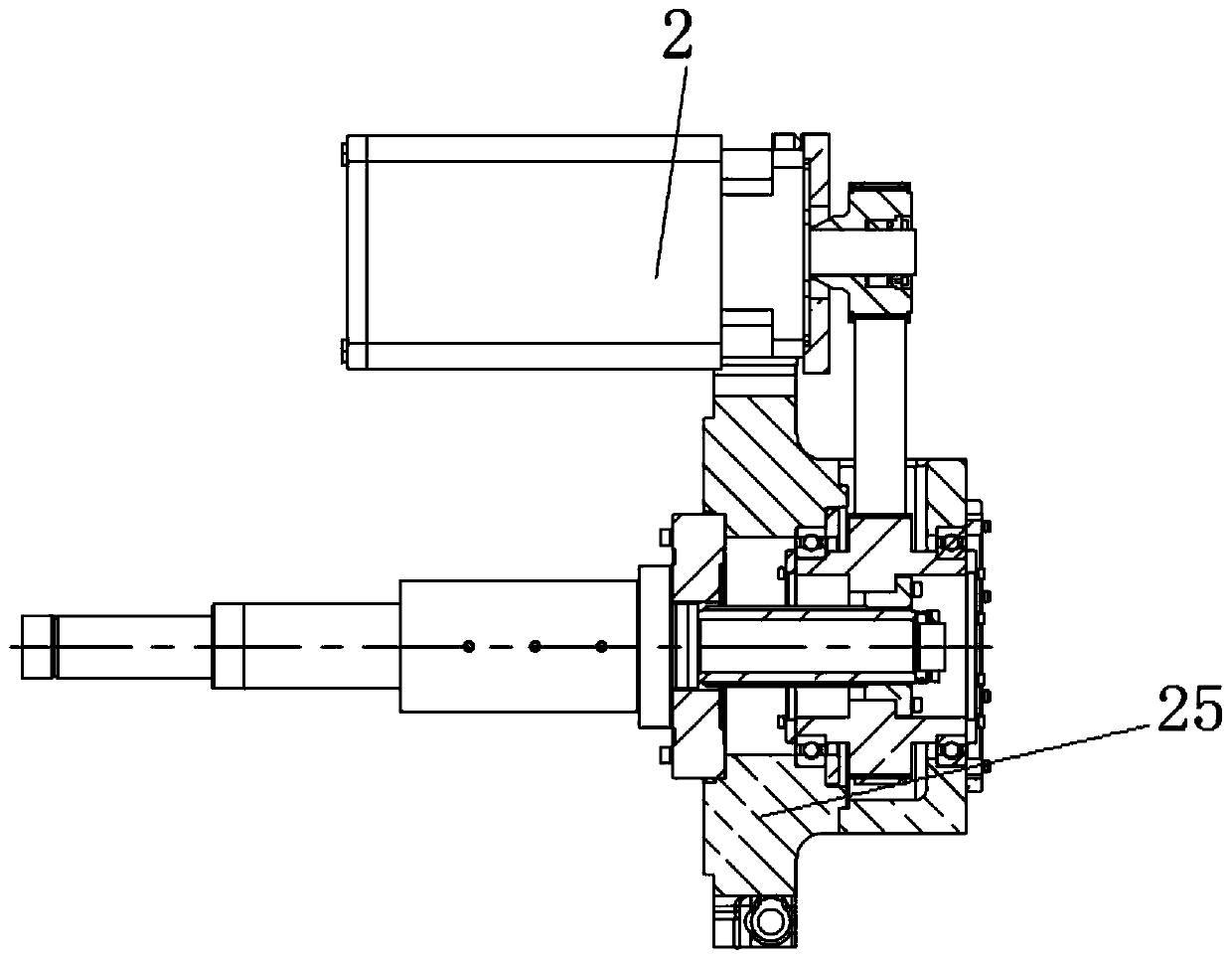
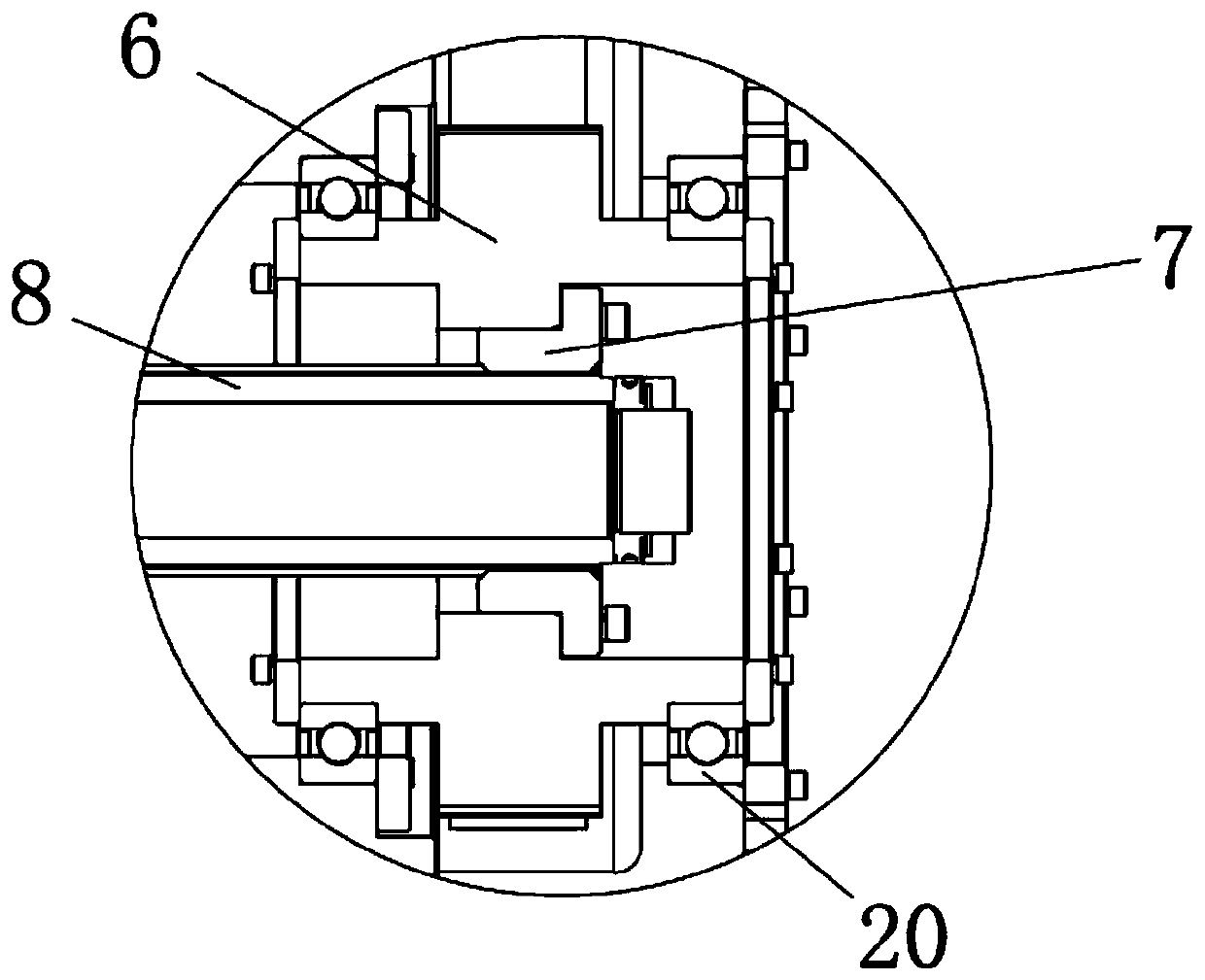
[0025] Embodiments of the present invention relate to an injection device of an electric injection molding machine, such as figure 1 - As shown in -6, it includes the injection platform main body seat 14, the pre-molding motor 1 and the pre-molding transmission cylinder 4, the pre-molding motor 1 with the main shaft facing left is installed on the upper part of the injection platform main body seat 14, and the pre-molding trans...


PUM


Abstract

The invention relates to an injection device of an electric injection molding machine. The injection device of the electric injection molding machine comprises an injection table main body seat, a pre-plasticizing motor and a pre-plasticizing transmission cylinder, wherein the pre-plasticizing motor with a main shaft facing to the right is mounted on the upper part of the injection table main bodyseat, the pre-plasticizing transmission cylinder is rotatably mounted in the injection table main body seat, a pre-plasticizing driven wheel is mounted on the outer ring of the pre-plasticizing transmission cylinder, the main shaft of the pre-plasticizing motor is connected with the pre-plasticizing driven wheel through a transmission wheel belt, a transmission shaft driving ring is installed atthe right end of the pre-plasticizing transmission cylinder, a transmission shaft sleeve engaged with the transmission shaft driving ring is installed in the right portion of the pre-plasticizing transmission cylinder, a transmission shaft seat capable of being separated is installed at the left end of the transmission shaft sleeve, a transmission shaft front cover is installed at the left end ofthe transmission shaft seat, and the left end of the transmission shaft front cover is connected with a screw. The injection device of the electric injection molding machine has the characteristics ofbeing high in ejection acceleration, short in response time, small in overall size, capable of being applied to injection molding machines with different models conveniently and the like.

Description

technical field [0001] The invention relates to the technical field of injection devices for injection molding machines, in particular to an injection device for electric injection molding machines. Background technique [0002] The injection unit is a very important part of the electric injection molding machine, and the injection acceleration and response time are the key data of the injection unit of the electric injection molding machine, which has a great impact on the injection performance. In the existing injection device of electric injection molding machine, the injection screw only rotates but does not move, and the injection driven wheel is fixed on the injection screw. This arrangement will cause the length of the injection stroke to not be fully utilized, resulting in an increase in the axial length of the injection unit. It is not conducive to the assembly of the injection unit and different bodies. At the same time, since the pre-molding unit is installed on t...

Claims


Application Information

Patent Timeline
Patent Type & Authority Applications(China)
IPC IPC(8): B29C45/47B29C45/50
CPCB29C45/47B29C45/5008
Inventor 王靖石则满
Owner 宁波力劲塑机智造有限公司
Why Eureka
Try Eureka