Water preparation device and water preparation method
A preparation device and container technology, applied in chemical instruments and methods, water/sewage treatment equipment, water/sewage treatment, etc., can solve the problems of poor overall polarization effect, low conversion rate and slow conversion speed of water preparation devices, etc. To achieve the effect of improving the sealing effect
- Summary
- Abstract
- Description
- Claims
- Application Information
AI Technical Summary
Problems solved by technology
Method used
Image
Examples
Embodiment 1
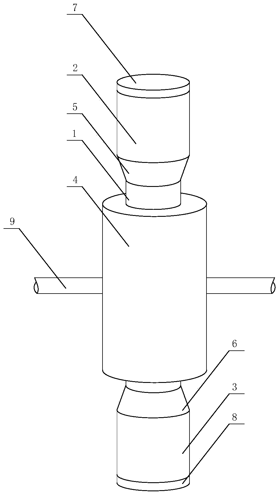
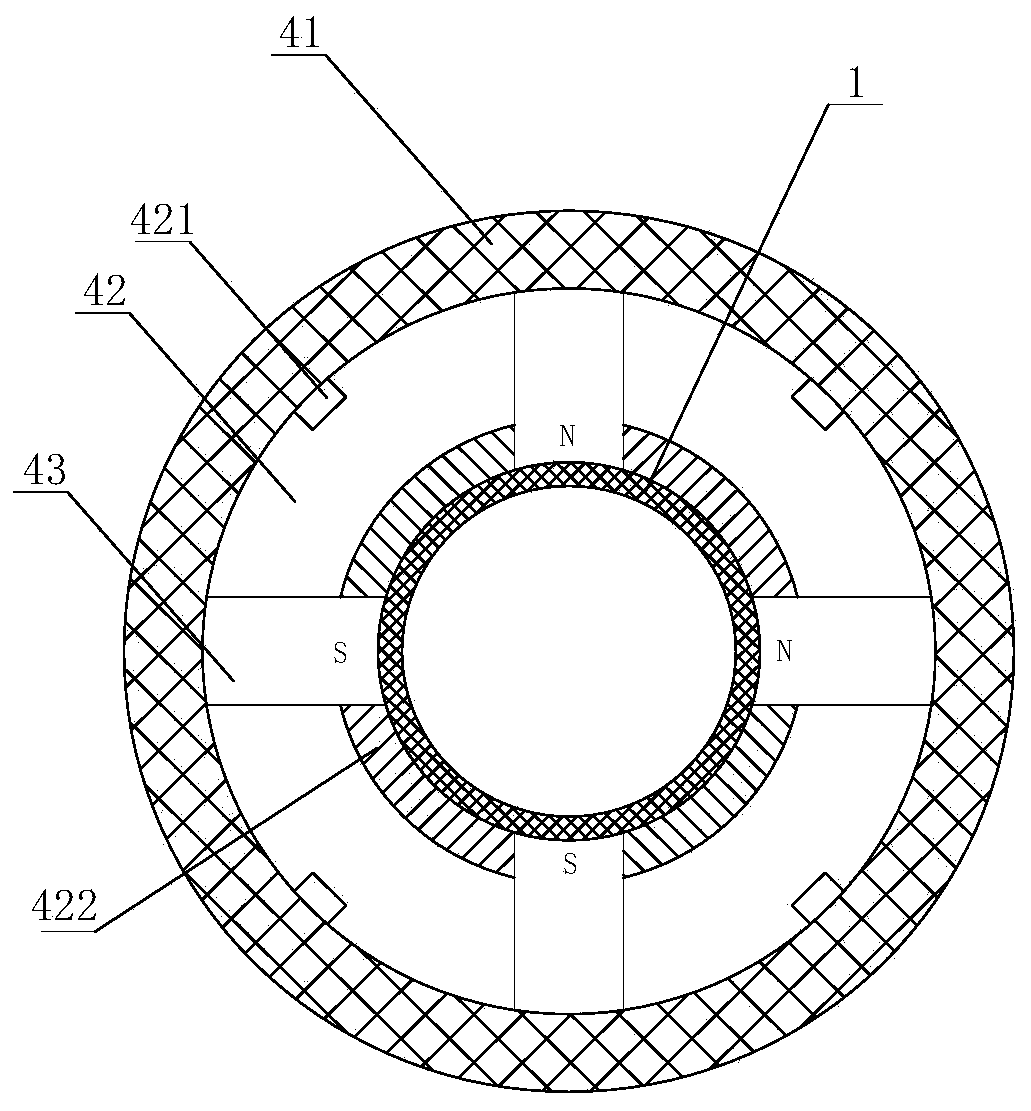
[0069] Such as figure 1 with figure 2 The shown water preparation device includes a first container 2 and a second container 3. An overflow section 1 is provided before the second container 3 and the first container 2, and the overflow section 1 communicates with the first container. The container 2 and the second container 3 are provided with a radiation part 4 outside the flow section 1, and the radiation part 4 is used to provide magnetic field and electromagnetic wave radiation to the fluid in the flow section; it also includes a rotating shaft 9, and the preparation device can surround The rotating shaft 9 is reversed so that the fluid flows between the first container 2 and the second container 3; a first diameter reducing section 5 is arranged between the first container 2 and the flow section 1, and the first diameter reducing section 5 The diameter of the end surface connected to the flow section 1 is larger than the inner diameter of the flow section 1, and a secon...
Embodiment 2
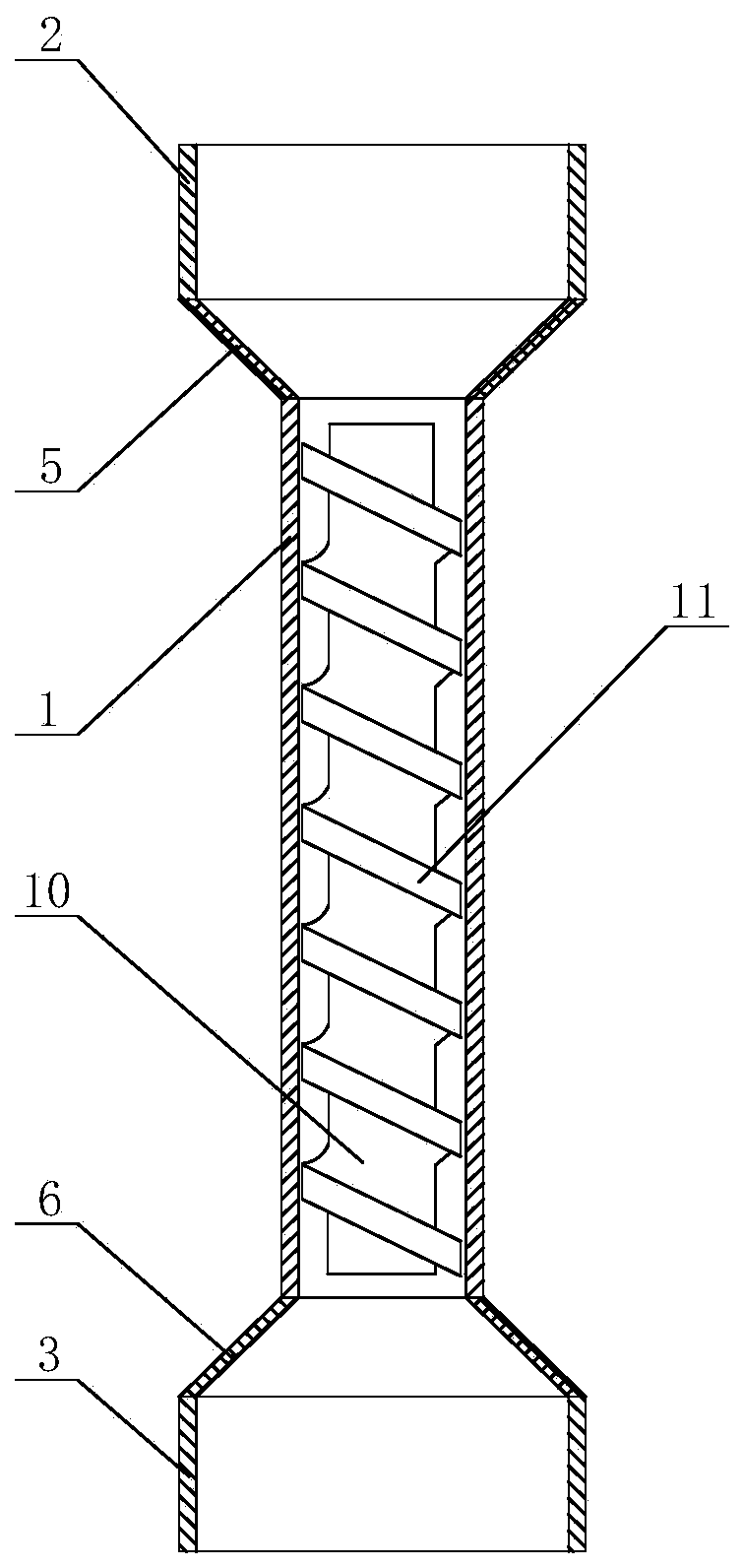
[0081] On the basis of Example 1, in order to further improve conversion efficiency and conversion rate, reduce the turnover times of preparation device simultaneously, reduce industrial energy consumption, as image 3 As shown, a flow-disturbing mechanism is provided in the flow-passing section 1 , and the flow-disturbing mechanism includes a cylinder 10 , and a helical blade 11 is provided on the outer wall of the cylinder 10 .
[0082] In some embodiments, a gap is provided between the outer edge of the spiral blade and the inner wall of the flow section, so that when the fluid passes through the flow section, most of the fluid moves from top to bottom along the spiral blade, and a small part of the fluid passes through the gap directly through the screw blades. By setting the gap, it can be avoided that when the water flow is large, the water flow between the upper and lower two adjacent spiral blades is too large to accumulate, resulting in poor circulation, and because t...
Embodiment 3
[0084] On the basis of Example 1, in order to further improve conversion efficiency and conversion rate, reduce the turnover times of preparation device simultaneously, reduce industrial energy consumption, as Figure 4 As shown, the spoiler mechanism includes a spoiler 20, and the spoiler 20 is provided with a flow hole 202; the spoiler 20 is also provided with an adjustment hole 201, and the adjustment mechanism in the adjustment hole 201, when When the amount of fluid on one side of the spoiler 20 is too large, the adjustment mechanism is opened to allow part of the fluid to pass through the adjustment hole 201 .
[0085] In some embodiments, the regulating mechanism can be an electric valve, and when the water flow in a single flow section is too large, the regulating hole can be opened by controlling the electric valve.
PUM
| Property | Measurement | Unit |
|---|---|---|
| Particle size | aaaaa | aaaaa |
Abstract
Description
Claims
Application Information
 - R&D
- Intellectual Property
- Life Sciences
- Materials
- Tech Scout
- Unparalleled Data Quality
- Higher Quality Content
- 60% Fewer Hallucinations
Browse by: Latest US Patents, China's latest patents, Technical Efficacy Thesaurus, Application Domain, Technology Topic, Popular Technical Reports.
© 2025 PatSnap. All rights reserved.Legal|Privacy policy|Modern Slavery Act Transparency Statement|Sitemap|About US| Contact US: help@patsnap.com


