A device for quickly measuring tool wear

A tool wear and tool technology, used in measuring/indicating equipment, manufacturing tools, metal processing equipment, etc., can solve the problems of low detection efficiency, error reporting and increase the workload of staff, to reduce labor intensity, improve operating efficiency, increase The effect of high friction

Active Publication Date: 2020-09-22
江苏厚道数控科技有限公司
View PDF5 Cites 0 Cited by
  • Summary
  • Abstract
  • Description
  • Claims
  • Application Information

AI Technical Summary

Problems solved by technology

[0008] The purpose of the present invention is to provide a device for quickly measuring tool wear, so as to solve the problem of low detection efficiency of tool wear devices in the prior art, and frequent error reporting increases the workload of staff

Method used


Image

  • A device for quickly measuring tool wear
  • A device for quickly measuring tool wear
  • A device for quickly measuring tool wear

Examples


Embodiment 1

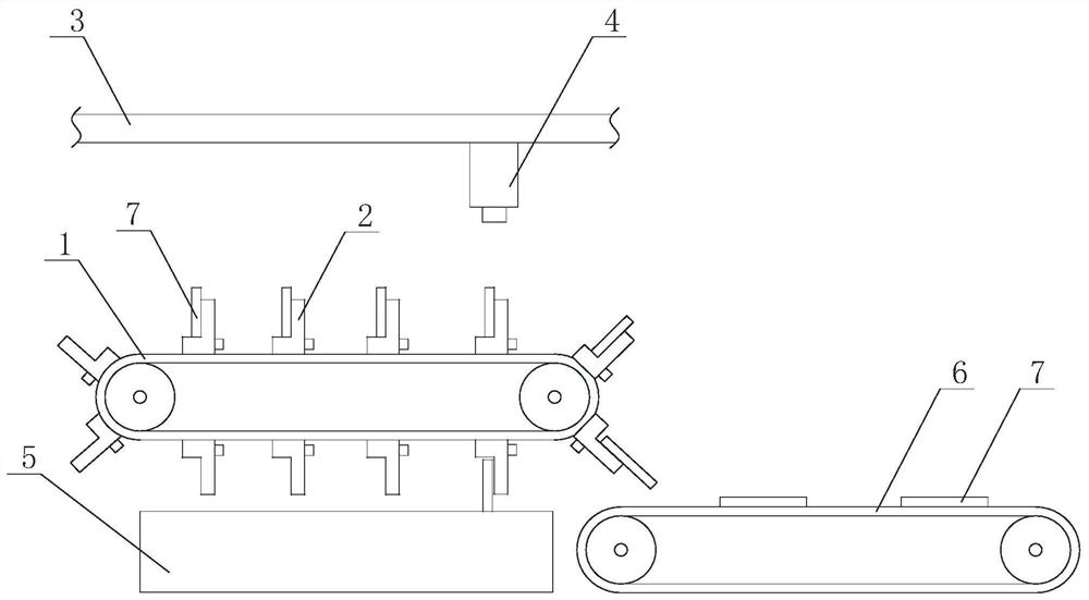
[0047] Such as figure 1 The shown device for quickly measuring tool wear includes a first conveyor belt 1, and a plurality of clamping mechanisms 2 are arranged on the first conveyor belt 1, and the clamping mechanisms 2 are capable of clamping a tool 7 to be detected. A tool wear detector 4 is arranged above the conveyor belt 1, and the tool wear detector 4 is used to detect a tool 7 to be detected, and a second conveyor belt 6 is arranged below the first conveyor belt 1, and the second conveyor belt 6 is used for transporting from The tool to be detected 7 disengaged from the clamping mechanism 2; the clamping mechanism 2 held includes a locked state and an unlocked state. In the locked state, the tool to be detected 7 is fixed relative to the clamping mechanism 2. In the unlocked state, The tool 7 to be detected can move relative to the installation groove.

[0048] In some embodiments, the tool wear detector 4 is installed on a slider, and the slider can move along the sl...

Embodiment 2

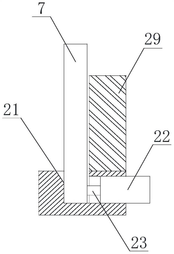
[0051] On the basis of Example 1, such as figure 2 As shown, the clamping mechanism 2 is provided with a slot 21 and an installation groove, the slot 21 is used to place the tool 7 to be detected, and a hydraulic cylinder 22 is arranged in the installation groove. In the locked state, the The piston rod 23 of the hydraulic cylinder 22 squeezes the side of the tool 7 to be detected, and the piston rod 23 and the inner wall of the slot 21 jointly form the clamping of the tool 7 to be detected; Reduced, the tool 7 to be detected can move relative to the slot 21.

[0052] In some embodiments, such as figure 2 As shown, the clamping mechanism as a whole is roughly a cylinder, and an arc-shaped baffle is arranged above the cylinder. Preferably, the center of the arc-shaped baffle is concentric with the center of the cylinder, and the position of the arc-shaped baffle is configured so that when When the clamping mechanism is located above the first conveyor belt, the arc-shaped b...

Embodiment 3

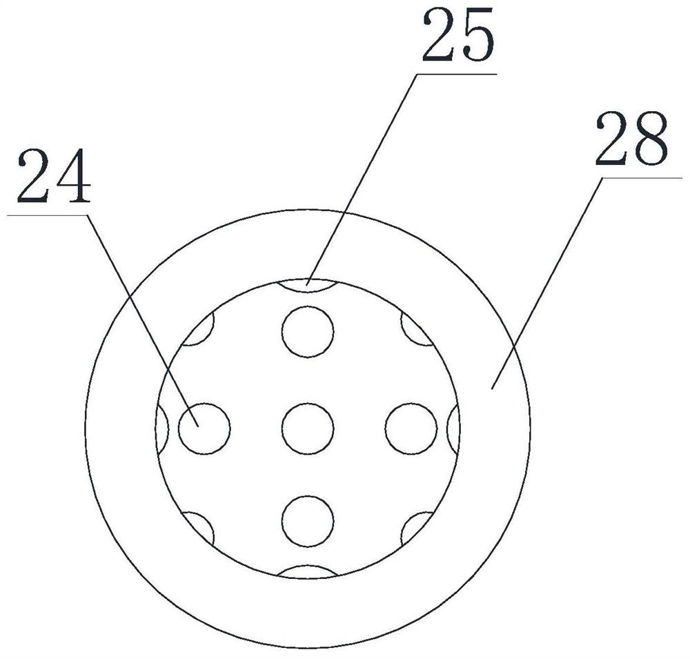
[0055] On the basis of the above examples, if image 3 and Figure 4 As shown, a protective sleeve 28 is also included, and the protective sleeve 28 can be tightly sleeved on the bottom of the tool 7 to be detected. The protective sleeve 28 is provided with a slot 26, and the size of the slot 26 is the same as that of the piston rod 23. match; the protective cover 28 is made of rubber material; the bottom of the protective cover 28 is provided with a through hole 24; the inner wall of the protective cover 28 is provided with several convex points 25; A clasp 27 is arranged inside the 26, and the clasp 27 is made of metal material.

[0056] In this embodiment, by setting the protective cover, on the one hand, it can play the role of a buffer layer, avoiding the surface of the piston rod from scratching the side of the tool to be detected, and increasing the friction between the two. On the other hand, the protective cover has a thickness and can The deformability can fill the...


PUM


Abstract

The invention discloses a device for rapidly measuring cutter abrasion. The device for rapidly measuring cutter abrasion comprises a first conveying belt, a plurality of clamping mechanisms are arranged on the first conveying belt, the clamping mechanisms can clamp a cutter to be detected, a cutter abrasion detector is arranged above the first conveying belt, the cutter abrasion detector is used for detecting the cutter to be detected, and a second conveying belt is arranged below the first conveying belt and is used for conveying the to-be-detected cutter separated from the clamping mechanisms. According to the device for rapidly measuring cutter abrasion, one-by-one detection of a plurality of to-be-detected cutters in the same batch can be realized, and the clamping mechanisms can be controlled to release the clamping of the to-be-detected cutters at the specified position according to the detection result, so that qualified or unqualified to-be-detected cutters are correspondinglyconveyed to different places for collection, thereby the automatic classification is realized, the overall operation efficiency of the system is effectively improved, frequent manual taking-out is notneeded, the labor intensity of workers is reduced, and the device has wide popularization value.

Description

technical field [0001] The invention relates to the technical field of tool detection equipment, in particular to a device for quickly measuring tool wear. Background technique [0002] Tool wear is a common phenomenon in machining, and the wear and wear state of the tool directly affect the precision, efficiency and economic benefits of machining. [0003] In recent years, with the wide application of high-performance CNC machine tools, FMS and CIMS, the efficiency and quality of machining have been significantly improved. At the same time, higher requirements have been put forward for fully automated production. One-to-one has developed to the current situation where one operator controls multiple devices. [0004] Therefore, tool failure in the form of tool life, wear, and tool breakage has an increasingly significant impact on the working state of the tool and the processing efficiency and precision of the system. [0005] In the prior art, researches on tool wear dete...

Claims


Application Information

Patent Timeline
Patent Type & Authority Patents(China)
IPC IPC(8): B23Q17/09B07C5/34B07C5/02B07C5/36
CPCB07C5/02B07C5/34B07C5/362B23Q17/09B23Q17/0904
Inventor 陈琪廖璘志黄河田泽明伍倪燕刘学航刘福华严瑞强
Owner 江苏厚道数控科技有限公司
Why Eureka
Try Eureka