Concrete pouring method for deep foundation pit

A concrete and deep foundation pit technology, applied in the field of concrete pouring, can solve the problems of inconvenient movement of hoisting equipment, reduce concrete pouring effect, concrete waste, etc., improve pouring effect and pouring efficiency, avoid concrete segregation and layering, and ensure uniformity The effect of sex and stability

Active Publication Date: 2020-02-07
CHINA RAILWAY CONSTR HEAVY IND
View PDF7 Cites 2 Cited by
  • Summary
  • Abstract
  • Description
  • Claims
  • Application Information

AI Technical Summary

Problems solved by technology

[0003] 1. Concrete pouring is carried out by pumping concrete directly to the area to be poured. This pouring method is difficult for the arm of the pump truck to expand to the pouring position due to space constraints. On the other hand, the traditional vertical conveying method of high-drop concrete is likely to cause aggregate separation and concrete Waste, thereby reducing the effect of concrete pouring;
[0004] 2. Use hoisting equipment to transport concrete to the area to be poured (such as a deep foundation pit). Due to the small space in the area to be poured, it is easy to cause inconvenient movement of the hoisting equipment, resulting in low efficiency in the process of conveying concrete

Method used


Image

  • Concrete pouring method for deep foundation pit
  • Concrete pouring method for deep foundation pit
  • Concrete pouring method for deep foundation pit

Examples


Embodiment 1

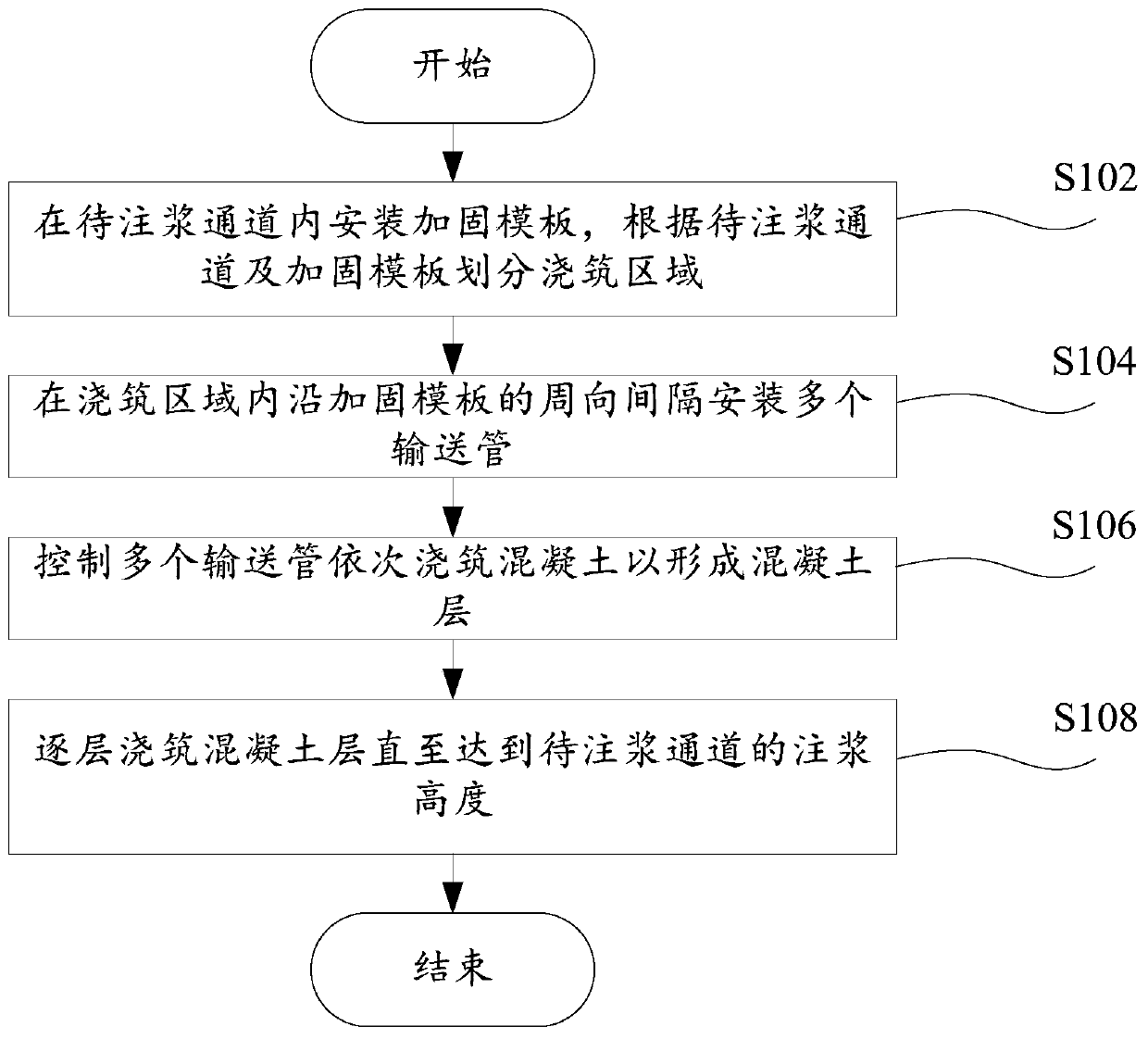
[0052] figure 1 A schematic flow diagram of the deep foundation pit concrete pouring method of the first embodiment of the present invention is shown, wherein the deep foundation pit concrete pouring method includes:

[0053] S102, installing a reinforcement formwork in the channel to be grouted, and dividing the pouring area according to the channel to be grouted and the reinforcement formwork;

[0054] S104, installing a plurality of conveying pipes at intervals along the circumference of the reinforced formwork in the pouring area;

[0055] S106, controlling a plurality of conveying pipes to sequentially pour concrete to form a concrete layer;

[0056] S108, pouring concrete layers layer by layer until reaching the grouting height of the channel to be grouted.

[0057] In detail, a reinforcement formwork is installed in the passage to be grouted (such as the reinforcement formwork is configured as a cylindrical structure), and the pouring area is divided according to the ...

Embodiment 2

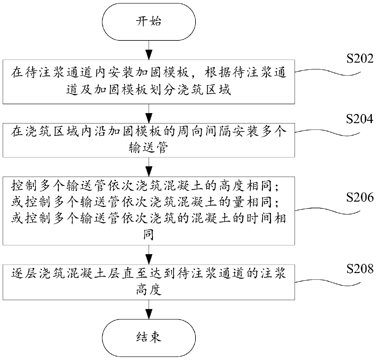
[0059] figure 2 Show the schematic flow chart of the deep foundation pit concrete pouring method of the second embodiment of the present invention, wherein, the deep foundation pit concrete pouring method comprises:

[0060] S202, installing a reinforcement formwork in the channel to be grouted, and dividing the pouring area according to the channel to be grouted and the reinforcement formwork;

[0061] S204, installing a plurality of conveying pipes at intervals along the circumference of the reinforced formwork in the pouring area;

[0062] S206, control multiple delivery pipes to pour concrete at the same height sequentially; or control multiple delivery pipes to sequentially pour concrete at the same amount; or control multiple delivery pipes to sequentially pour concrete at the same time;

[0063] S208, pouring concrete layers layer by layer until reaching the grouting height of the channel to be grouted.

[0064] In detail, since the shape of the channel to be grouted...

Embodiment 3

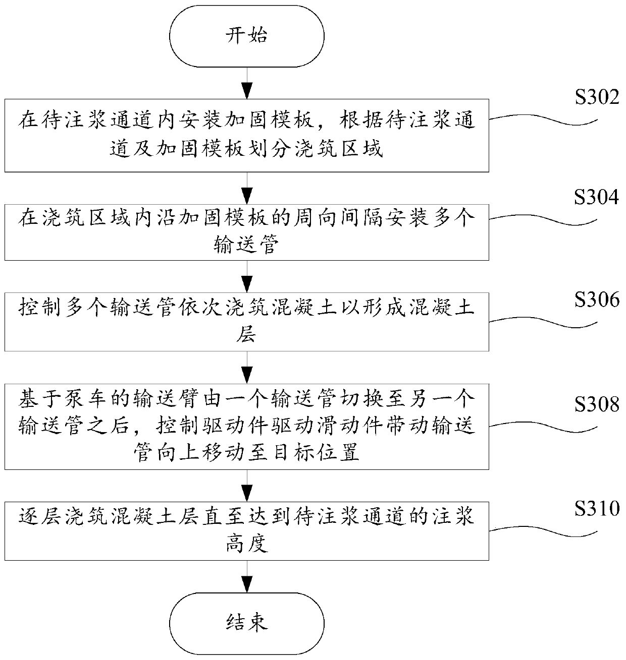
[0067] image 3 A schematic flow chart of the deep foundation pit concrete pouring method of the third embodiment of the present invention is shown, wherein the deep foundation pit concrete pouring method includes:

[0068] S302, installing a reinforcement formwork in the channel to be grouted, and dividing the pouring area according to the channel to be grouted and the reinforcement formwork;

[0069] S304, installing a plurality of conveying pipes at intervals along the circumference of the reinforced formwork in the pouring area;

[0070] S306, controlling a plurality of conveying pipes to sequentially pour concrete to form a concrete layer;

[0071] S308, after the delivery arm of the pump truck is switched from one delivery pipe to another delivery pipe, the driving part is controlled to drive the sliding part to drive the delivery pipe to move upward to the target position;

[0072] S310, pouring concrete layers layer by layer until reaching the grouting height of the ...


PUM


Abstract

The invention provides a concrete pouring method for a deep foundation pit. The concrete pouring method for the deep foundation pit is used for concrete pouring equipment, and the concrete pouring equipment comprises a conveying pipe. The concrete pouring method for the deep foundation pit comprises the following steps: installing a reinforcing die plate in a channel to be grouted, and dividing pouring areas according to the channel to be grouted and the reinforcing die plate; installing a plurality of conveying pipes at intervals in each pouring area in the circumferential direction of the reinforcing die plate; controlling the plurality of conveying pipes to sequentially pour concrete to form concrete layers; and pouring the concrete layers one by one until a grouting of the channel to be grouted is reached. According to the concrete pouring method for the deep foundation pit, the pouring areas are divided by installing the plurality of conveying pipes at intervals in each pouring area in the circumferential direction of the reinforcing die plate; and each area is equipped with one conveying pipe, overall and comprehensive pouring working is carried out on the pouring areas by virtue of the conveying pipes, and the use needs of different pouring spaces are met in the case of ensuring a pouring effect, so that continuous and cyclic concrete pouring working the circumferentialdirection of the reinforcing die plate is realized, and then the concrete pouring quality can be ensured.

Description

technical field [0001] The invention relates to the technical field of concrete pouring, in particular to a concrete pouring method for a deep foundation pit. Background technique [0002] In related technologies, there are mainly two ways of pouring concrete: [0003] 1. Concrete pouring is carried out by pumping concrete directly to the area to be poured. This pouring method is difficult for the arm of the pump truck to expand to the pouring position due to space constraints. On the other hand, the traditional vertical conveying method of high-drop concrete is likely to cause aggregate separation and concrete Waste, thereby reducing the effect of concrete pouring; [0004] 2. Use hoisting equipment to transport concrete to the area to be poured (such as a deep foundation pit). Due to the small space in the area to be poured, it is easy to cause inconvenient movement of the hoisting equipment, resulting in low efficiency in the process of conveying concrete. Contents of ...

Claims


Application Information

Patent Timeline
Patent Type & Authority Applications(China)
IPC IPC(8): E02D15/02
CPCE02D15/02E02D2250/0023
Inventor 刘飞香张海涛吕展鹏刘仁杰苏杰宋效凯蒋永飞
Owner CHINA RAILWAY CONSTR HEAVY IND
Why Eureka
Try Eureka