Rigid splicing structure, assembly-type wall and manufacturing and mounting method

A prefabricated and rigid technology, applied in the direction of walls, building components, building structures, etc., can solve problems such as complex installation, achieve quick installation, improve assembly efficiency, and improve reliability

Pending Publication Date: 2020-02-07
BEIJING NEW BUILDING MATERIALS PLC
View PDF7 Cites 2 Cited by
  • Summary
  • Abstract
  • Description
  • Claims
  • Application Information

AI Technical Summary

Problems solved by technology

[0004] The technical problem solved by this application is to provide a rigid splicing structure and a prefabricated wall made of it, as well as a method for preparing and installing the prefabricated wall, so as to solve the construction problem of complex installation

Method used


Image

  • Rigid splicing structure, assembly-type wall and manufacturing and mounting method
  • Rigid splicing structure, assembly-type wall and manufacturing and mounting method
  • Rigid splicing structure, assembly-type wall and manufacturing and mounting method

Examples


Embodiment 1

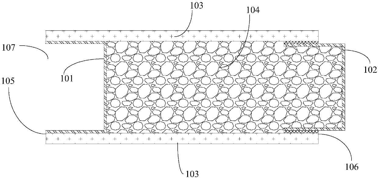
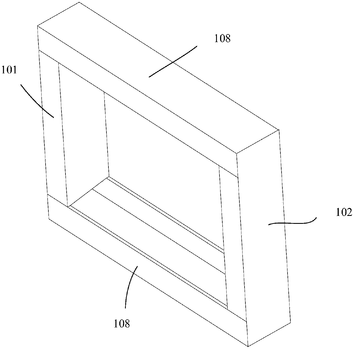
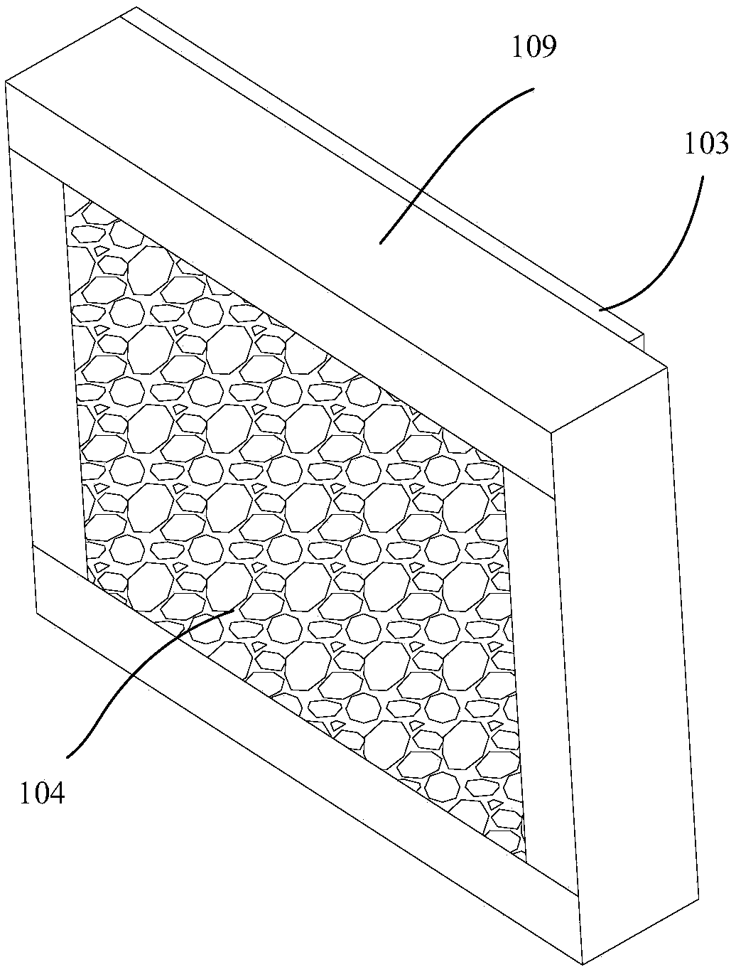
[0035] Figure 1 to Figure 5 It is Embodiment 1 of the assembled wall body of the present invention. Such as Figure 1 to Figure 5 As shown, the prefabricated wall includes a plurality of wall units 1 that are linearly joined together, wherein the wall unit 1 includes a keel frame 109 and wall panels 103 that are arranged on both sides of the keel frame 109 to close the keel frame 109, and The thermal insulation material 104 is filled in the keel frame 109 , and the thermal insulation material 3 is bonded to the wall panel 103 . In particular, the two ends in the length direction of the wall unit 4 respectively form a protruding end 106 and a recessed end 105 for insertion. The prefabricated wall is spliced ​​by the wall units in sequence, which can realize fast and convenient assembly, dry construction, water saving and energy saving, fast and efficient, improve construction efficiency by more than 70%, and can also reduce garbage pollution on the construction site, and has...

Embodiment 2

[0040] Image 6 It is the second embodiment of the fabricated wall of the present invention. The substantial difference between the second embodiment and the first embodiment is that the keel frame also includes vertical keels.

[0041] Specifically, as Image 6 As shown, the keel frame 109 also includes a vertically arranged vertical keel 3, which is parallel to the first keel 101 and the second keel 102, and the two ends of the vertical keel 3 are respectively fixed to two horizontal keels 108 arranged up and down. .

[0042] Compared with the first embodiment, this embodiment can improve the overall strength.

Embodiment 3

[0044] Figure 7 It is the third embodiment of the prefabricated wall of the present invention. The substantial difference between the third embodiment and the first embodiment is that: there is also a filling material between the wall units.

[0045] Specifically, as Figure 7 As shown, a filling material 4 is sandwiched between two adjacent wall units 1, and the filling material 4 is arranged in the gap between the first keel 101 and the second keel 102 of the adjacent wall unit 1, and The first keel 101 and the second keel 102 press the filling material 4 to block the sound propagation path between the two wall units 1 and play a certain role of heat insulation. The filling material 4 is pre-fixed at the joint of any wall unit 1 before the two wall units 1 are joined, and after the two wall units 1 are joined, the two wall units 1 squeeze the filling material 4 .

[0046] Compared with the first embodiment, this embodiment can improve the overall sound insulation perform...


PUM


Abstract

The invention discloses a rigid splicing structure, an assembly-type wall and a manufacturing and mounting method. The rigid splicing structure comprises two spliced wall units, a recessed end and a protruding end, a first keel is arranged at the recessed end, an opening is formed in one end of the first keel and faces the protruding end, the protruding end comprises a second keel, the second keelprotrudes from the end surface of the corresponding wall unit, and the second keel is inserted into the first keel from an opening and penetrates through a wall panel through a screw to fix the second keel and the first keel. The wall units of the assembly-type wall are spliced and fixed through the rigid splicing structure, and the manufacturing and mounting method of the assembly-type wall mainly comprises the following steps of keel frame splicing, protruding and recessed end forming by splicing, and inserting connecting for fixing; and the invention relates to the field of construction, and according to the rigid splicing structure, the assembly-type wall composed by the rigid splicing structure and the manufacturing and mounting method of the assembly-type wall, the construction problems of complex mounting are solved accordingly.

Description

technical field [0001] The application relates to the field of construction, and in particular to a rigid splicing structure, a prefabricated wall and a preparation and installation method. Background technique [0002] Traditional housing construction, especially steel structure and integrally poured cement structure buildings, the interior of the building is empty except for the structural load-bearing columns, and internal partition walls are set according to the needs of specific housing uses to divide the entire floor into functional rooms one by one. The existing interior partition walls often use light steel keels and gypsum boards for on-site construction, which leads to messy construction sites, too much construction waste such as waste and leftover materials, and is not suitable for the recycling of detachable partition walls. Large, the labor cost is too high, and the construction dimensional accuracy is low. In response to the country's policy guidelines for new...

Claims


Application Information

Patent Timeline
Patent Type & Authority Applications(China)
IPC IPC(8): E04B2/74E04B2/82
CPCE04B2/7407E04B2/7409
Inventor 赵永生
Owner BEIJING NEW BUILDING MATERIALS PLC
Why Eureka
Try Eureka