A cam-pressurized cone-disk continuously variable transmission

A continuously variable transmission, cone-disc technology, applied in the direction of gear lubrication/cooling, belt/chain/gear, transmission, etc., can solve the problems of difficult to achieve flexible elements, asymmetry of pressurized cam mechanism, asymmetry, etc. Achieve the effect of compact structure, improved power density and improved lifespan

Active Publication Date: 2020-09-15
杭州肇鹏科技有限公司
View PDF11 Cites 0 Cited by
  • Summary
  • Abstract
  • Description
  • Claims
  • Application Information

AI Technical Summary

Problems solved by technology

In the above literature, the pressurizing mechanism is arranged on the side of the fixed cone, which has a compact structure, but it is difficult to achieve a balance between the axial pressure required by the flexible element and the transmission efficiency, and due to the existence of the speed ratio, the working conditions of the main and driven shafts are not Symmetrical, so the pressurized cam mechanism on the fixed cone side of the main and driven shafts is not symmetrical, and should be treated differently

Method used


Image

  • A cam-pressurized cone-disk continuously variable transmission
  • A cam-pressurized cone-disk continuously variable transmission
  • A cam-pressurized cone-disk continuously variable transmission

Examples


Embodiment 1

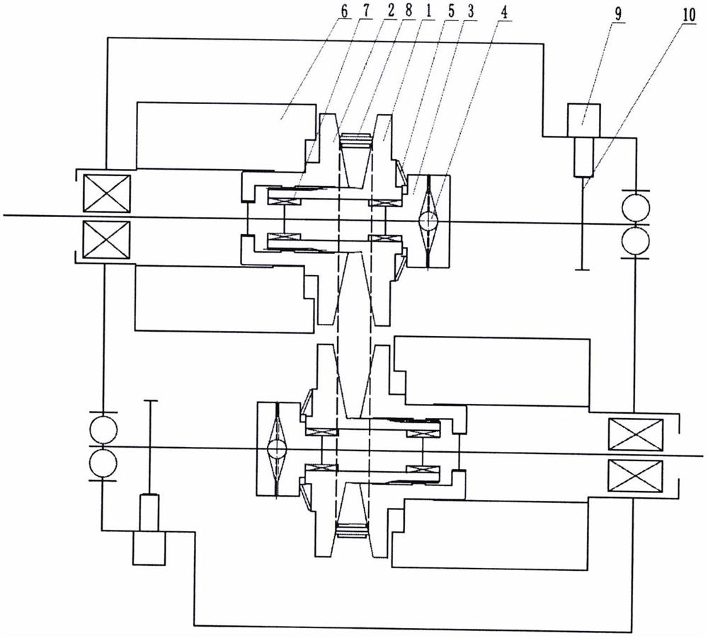
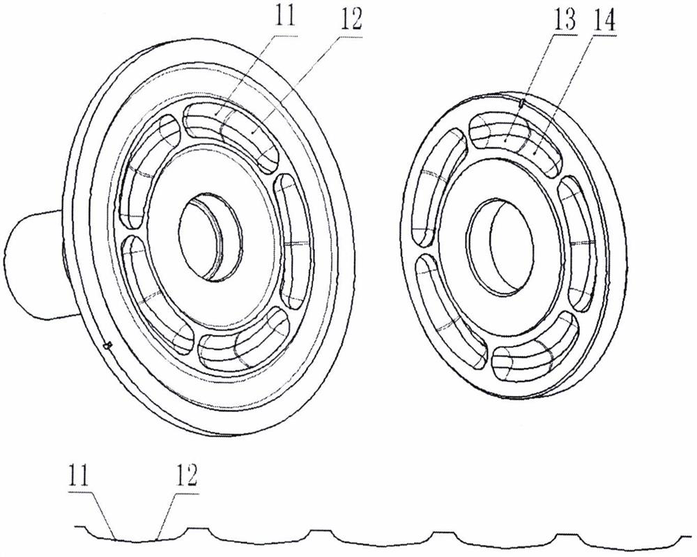
[0052] A cam-pressurized conical-disk type continuously variable transmission, comprising a driving conical-disc group arranged on a driving shaft, a driven conical-disk group arranged on a driven shaft, an end face cam pressurizing mechanism and a steel chain, the The active cone group includes an active fixed cone and an active driven cone, and the driven cone group includes a driven fixed cone and a driven driven cone, and the active and driven cone groups are respectively Working with the steel chain in lubricating oil environment, the back of the driving fixed cone and the driven fixed cone are equipped with an end cam pressurization mechanism, and the end cam pressurization mechanism includes a driving cam and a slave cam arranged axially opposite As for the movable cam, n V-shaped raceways uniformly distributed along the circumferential direction are respectively provided on the axially opposite end surfaces of the driving cam and the driven cam, and each of the V-shaped...

Embodiment 2

[0062] A cam-pressurized conical-disk type continuously variable transmission, comprising a driving conical-disc group arranged on a driving shaft, a driven conical-disk group arranged on a driven shaft, an end face cam pressurizing mechanism and a steel chain, the The active cone group includes an active fixed cone and an active driven cone, and the driven cone group includes a driven fixed cone and a driven driven cone, and the active and driven cone groups are respectively Working with the steel chain in lubricating oil environment, the back of the driving fixed cone and the driven fixed cone are equipped with an end cam pressurization mechanism, and the end cam pressurization mechanism includes a driving cam and a slave cam arranged axially opposite As for the movable cam, n V-shaped pressure surfaces uniformly distributed along the circumferential direction are arranged on the axially opposite end surfaces of the driving cam and the driven cam, and each of the V-shaped pre...

Embodiment 3

[0066] A cam-pressurized conical-disk type continuously variable transmission, comprising a driving conical-disc group arranged on a driving shaft, a driven conical-disk group arranged on a driven shaft, an end face cam pressurizing mechanism and a steel chain, the The active cone group includes an active fixed cone and an active driven cone, and the driven cone group includes a driven fixed cone and a driven driven cone, and the active and driven cone groups are respectively Working with the steel chain in lubricating oil environment, the back of the driving fixed cone and the driven fixed cone are equipped with an end cam pressurization mechanism, and the end cam pressurization mechanism includes a driving cam and a slave cam arranged axially opposite As for the movable cam, n V-shaped raceways uniformly distributed along the circumferential direction are respectively provided on the axially opposite end surfaces of the driving cam and the driven cam, and each of the V-shaped...


PUM


Abstract

The invention relates to a cam-pressed cone-plate type continuously variable transmission. The cam-pressed cone-plate type continuously variable transmission includes a driving cone-plate set arrangedon a driving shaft, a driven cone-plate set arranged on a driven shaft, an end-face cam-pressed mechanism, and a steel flexible transmission element. By setting the angle of a V-shaped groove of theend-face cam-pressed mechanism and the association relationship of related parts, the dynamic response of a system is significantly improved, the service life of the overall system is prolonged, and the system reliability is also improved.

Description

technical field [0001] The invention belongs to the field of power mechanical transmissions, and in particular relates to a cam-pressurized cone-disk continuously variable transmission. Background technique [0002] Driven by factors such as energy, environmental protection, and market competition, the automatic transmissions of traditional fuel vehicles and new energy vehicles need to be more efficient and reliable, and the cost needs to be continuously reduced. The light weight and miniaturization of automobiles and the increase in cruising range require the size of the battery pack, which also drives the structure of the transmission to be more compact. At the same time, a more compact structure and cooling, heat dissipation, etc. also need to be better balanced. [0003] In the prior art, the pressurizing mechanism is mostly set on the side of the moving cone, such as the method of using the end face cam and the hydraulic system to pressurize the moving cone of the cont...

Claims


Application Information

Patent Timeline
Patent Type & Authority Patents(China)
IPC IPC(8): F16H25/04F16H57/04
CPCF16H25/04F16H57/0415
Inventor 不公告发明人
Owner 杭州肇鹏科技有限公司
Why Eureka
Try Eureka