Sealed rotating structure at the rotating shaft in wind power generation equipment

A technology of wind power generation equipment and rotating structure, which is applied to wind power generators, wind power motors consistent with the wind direction, sealing of motors, etc., which can solve problems such as reduced service life, blade breakage and damage, and complex structure of the adjustment device, so as to maintain stability Rotation, the effect of increasing the service life

Active Publication Date: 2020-07-14
中电投新疆能源化工集团哈密有限公司
View PDF7 Cites 1 Cited by
  • Summary
  • Abstract
  • Description
  • Claims
  • Application Information

AI Technical Summary

Problems solved by technology

[0002] As the energy shortage becomes more and more serious, and people's awareness of environmental protection continues to increase, people pay more and more attention to clean energy. Wind power generation equipment is a device that uses wind power to generate electricity without additional pollution and can be effectively As a supplement to conventional electricity, wind power generation equipment is usually erected in areas with sufficient wind power, and the wind drives the blades to rotate, thereby generating power as power. Since wind power generation equipment is used in a natural environment, it is easily eroded by rainwater, and moisture penetrates through the gaps. If it enters the equipment, it will cause damage to the parts of each part and reduce the service life. At the same time, the wind force is constantly changing during the use of the equipment, especially in strong winds. If the angle of the blades is not adjusted, the blades may break damage, and the existing regulating device has a complex structure, and generally needs to be controlled by the power system, which is very troublesome. For this reason, the present invention proposes a sealing and rotating structure at the rotating shaft in wind power generation equipment to solve the above problems

Method used


Image

  • Sealed rotating structure at the rotating shaft in wind power generation equipment
  • Sealed rotating structure at the rotating shaft in wind power generation equipment
  • Sealed rotating structure at the rotating shaft in wind power generation equipment

Examples


Embodiment Construction

[0019] The following will clearly and completely describe the technical solutions in the embodiments of the present invention with reference to the accompanying drawings in the embodiments of the present invention. Obviously, the described embodiments are only some, not all, embodiments of the present invention. Based on the embodiments of the present invention, all other embodiments obtained by persons of ordinary skill in the art without making creative efforts belong to the protection scope of the present invention.

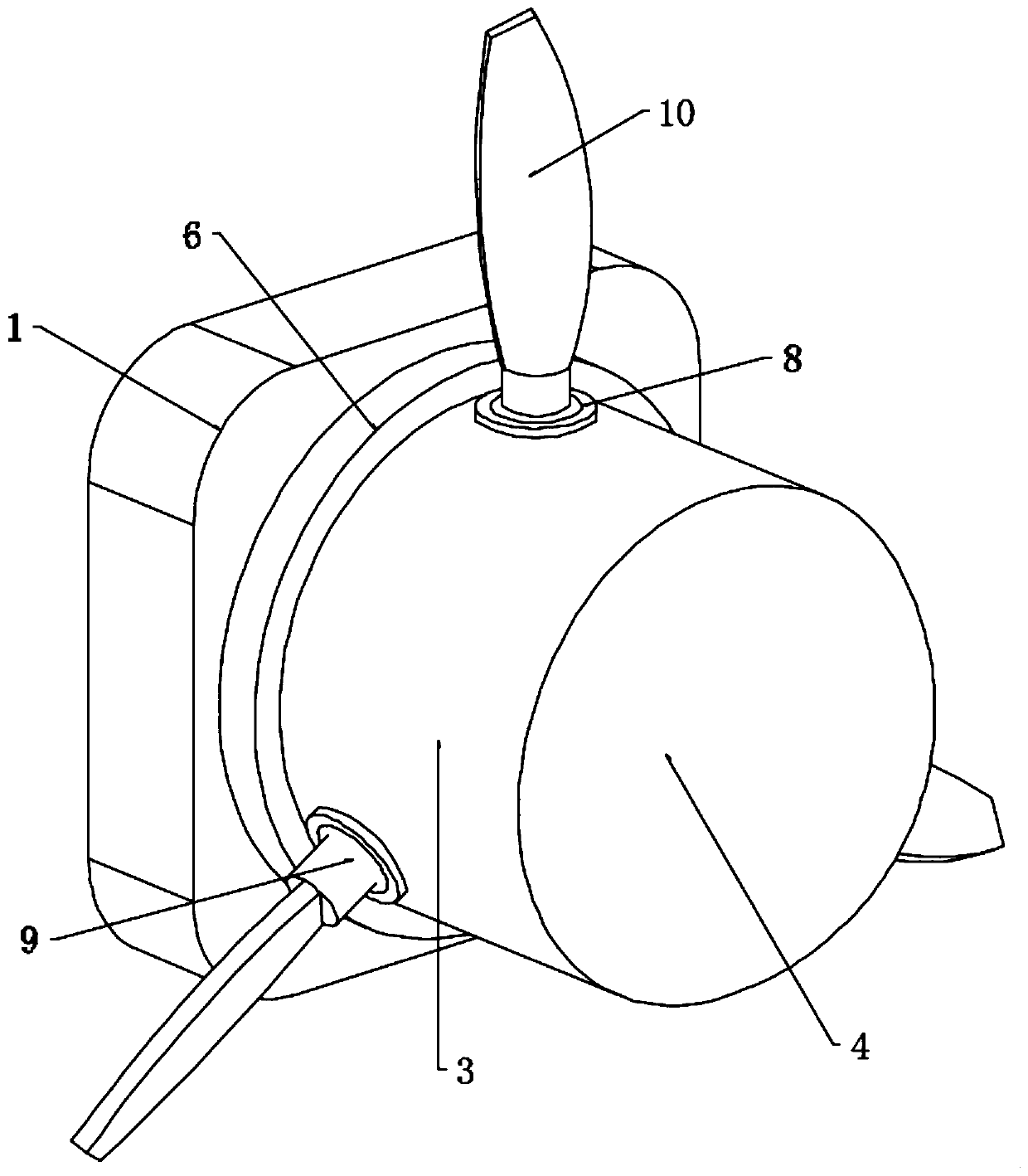
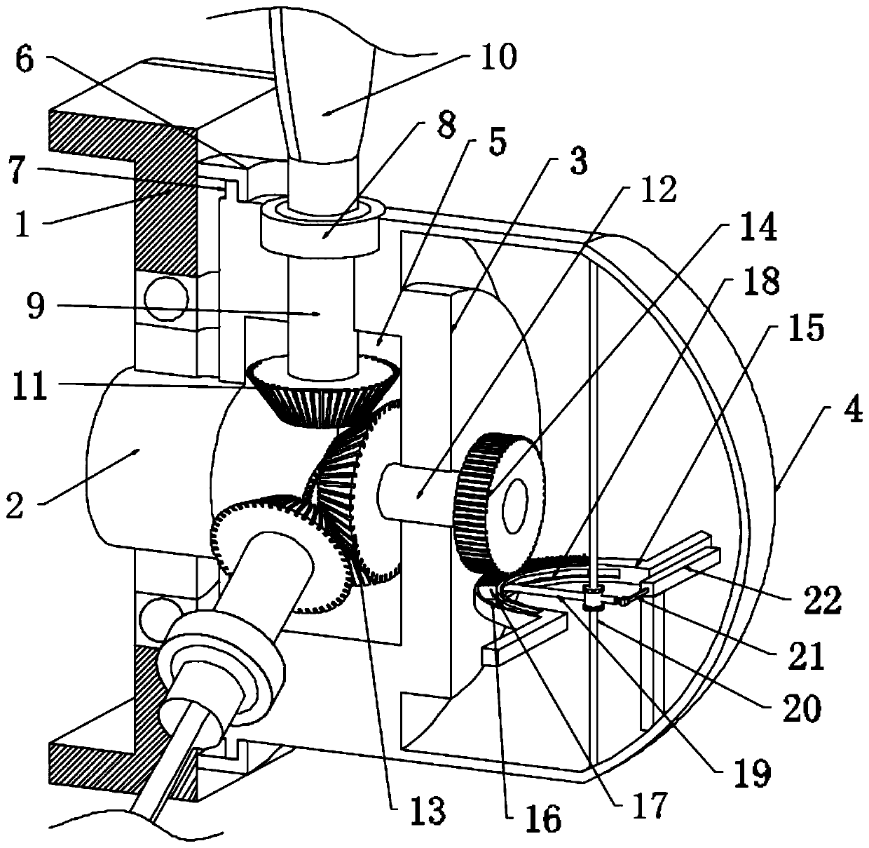
[0020] see Figure 1 to Figure 3 , the present invention provides a technical solution: a sealed rotating structure at the rotating shaft in wind power generation equipment, including a nacelle 1, a rotating shaft 2 is rotatably connected to the nacelle 1, and the rotating shaft 2 is fixedly connected to the hub 3, and the The wheel hub 3 is integrally formed with an end cover 4, and the wheel hub 3 is provided with a cavity 5, the nacelle 1 is fixedly install...


PUM


Abstract

The invention discloses a sealing and rotating structure at the rotating shaft in wind power generation equipment, including a nacelle, the nacelle is rotatably connected with a rotating shaft, and the rotating shaft is fixedly connected with a wheel hub, and the wheel hub is integrally formed with an end cover, and the wheel hub A cavity is arranged inside, a rain shield is fixedly installed on the nacelle, and a sealing ring is arranged on the wheel hub, a sealed bearing is fixedly installed on the wheel hub, and a connecting rod is connected to the sealed bearing in rotation, and a connecting rod is mounted on the connecting rod The blades are fixedly installed. When encountering strong wind and exceeding a certain limit, the centrifugal force on the slider increases, and it moves against the elastic force of the spring and the friction force of the second chute, thereby driving the push-pull rod to move and increasing it through the action of the lever. The torque makes the arc-shaped rack move, and finally achieves the purpose of automatically adjusting the blades without additional motor drive, and finally forms a certain balance to maintain the smooth rotation of the blades for continuous power generation.

Description

technical field [0001] The invention relates to the technical field of wind power generation, in particular to a sealing and rotating structure at a rotating shaft in wind power generation equipment. Background technique [0002] As the energy shortage becomes more and more serious, and people's awareness of environmental protection continues to increase, people pay more and more attention to clean energy. Wind power generation equipment is a device that uses wind power to generate electricity without additional pollution and can be effectively As a supplement to conventional electricity, wind power generation equipment is usually erected in areas with sufficient wind power, and the wind drives the blades to rotate, thereby generating power as power. Since wind power generation equipment is used in a natural environment, it is easily eroded by rainwater, and moisture penetrates through the gaps. If it enters the equipment, it will cause damage to the parts of each part and r...

Claims


Application Information

Patent Timeline
Patent Type & Authority Patents(China)
IPC IPC(8): F16J15/16F03D1/06F03D7/04F03D80/00
CPCF16J15/16F03D1/0675F03D1/0691F03D7/0224F03D7/041F03D80/00F03D1/0658Y02E10/72
Inventor 吴奕学竺键彬竺赛飞
Owner 中电投新疆能源化工集团哈密有限公司
Why Eureka
Try Eureka