
Air source heat pump system capable of preventing frost deposition

An air source heat pump and frost accumulating technology, which is applied to lighting and heating equipment, compressors with reversible cycles, subcoolers, etc., can solve the problems that the economizer cannot get refrigerant, the enthalpy of the compressor increases, and the subcooling degree of the unit is low And other issues

Inactive Publication Date: 2020-02-07
GUANGDONG NEW ENERGY TECH DEV
View PDF7 Cites 0 Cited by
  • Summary
  • Abstract
  • Description
  • Claims
  • Application Information

AI Technical Summary

Problems solved by technology

[0003] When the unit of the air source heat pump system is operating at low temperature, due to the high pressure ratio of the compressor, the exhaust temperature is relatively high. "phenomenon" to lower the exhaust gas temperature by slight "liquid carrying", but long-term liquid carrying will cause the refrigerant on the condensation side of the unit to migrate to the gas-liquid separator of the unit, and in the case of high-temperature outlet water, the subcooling degree of the unit will be very high Low, or even no supercooling, resulting in the economizer being unable to get the refrigerant, resulting in ineffective enthalpy increase of the compressor. In addition, when the unit defrosts in winter, due to incomplete defrosting, frost often accumulates on the bottom of the fins, which lasts for a long time. After the formation of the "iceberg" phenomenon

Method used


Image

  • Air source heat pump system capable of preventing frost deposition
  • Air source heat pump system capable of preventing frost deposition

Examples


Embodiment Construction

[0019] The technical solutions in the embodiments of the present invention will be clearly and completely described below in conjunction with the embodiments of the present invention. Apparently, the described embodiments are only some of the embodiments of the present invention, not all of them. Based on the embodiments of the present invention, all other embodiments obtained by persons of ordinary skill in the art without creative efforts fall within the protection scope of the present invention.

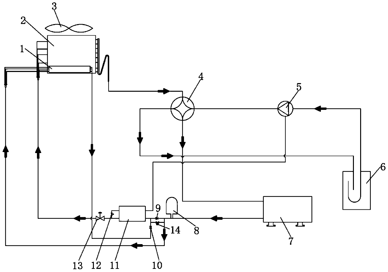
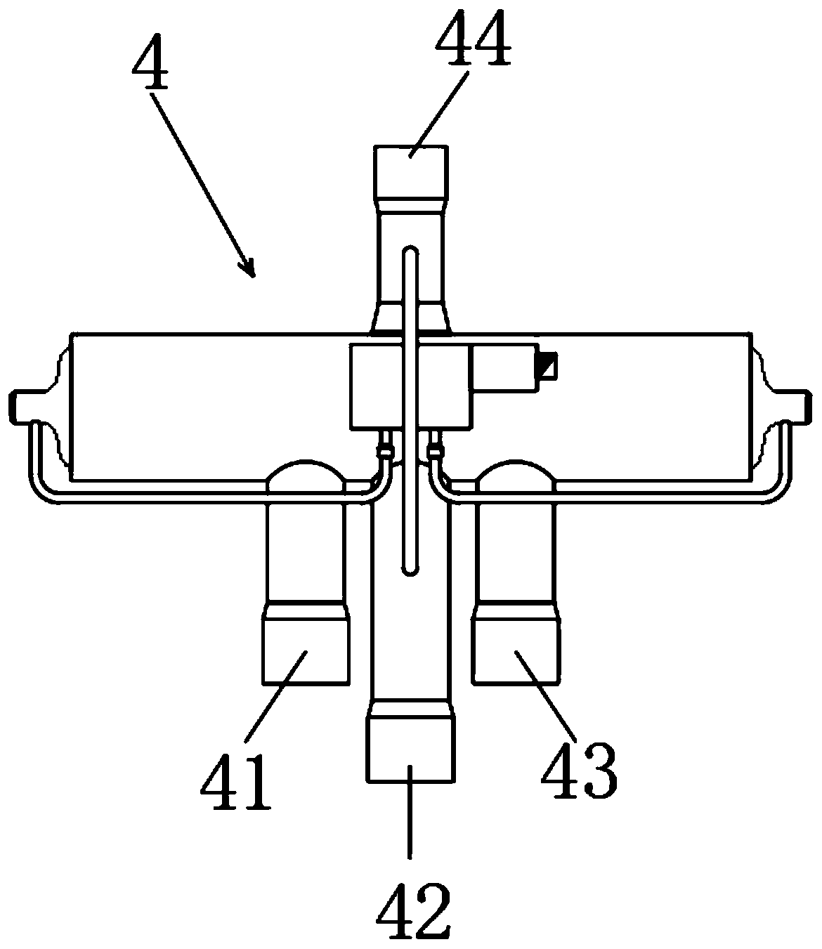
[0020] see Figure 1-2 As shown, an anti-frost air source heat pump system includes a finned heat exchanger 2, a four-way valve 4, a compressor 5, a gas-liquid separator 6, a shell-and-tube heat exchanger 7 and an economizer 11, and the four-way The valve 4 is provided with an E pipe 41, an S pipe 42, a C pipe 43 and a D pipe 44, the compressor 5 is provided with an exhaust port, a suction port and an enthalpy increasing port, and the economizer 11 is provided with an auxiliary ro...


PUM


Abstract

The invention discloses an air source heat pump system capable of preventing frost deposition. The air source heat pump system comprises a fin heat exchanger, a four-way valve, a compressor, a gas-liquid separator, a housing-tube heat exchanger and an economizer, wherein the four-way valve is provided with an E tube, an S tube, a C tube and a D tube; and the compressor is provided with an exhaustport, an air suction port and an enthalpy increasing port. According to the air source heat pump system, a one-way valve and an electromagnetic valve are additionally arranged in front of the economizer, a natural subcooler is additionally arranged at the front end of the outdoor side fin heat exchanger, the supercooling degree of a refrigerant is increased through forced heat exchange of an outdoor fan, then the refrigerant flows back to an inlet of the economizer, the supercooling refrigerant passing through the natural subcooler ensures that enough refrigerant flows into an enthalpy increasing pipeline of the compressor, and the optimal capacity of the compressor can be exerted; and meanwhile, after outdoor side low-temperature air passes through the natural subcooler, the temperature rises, so that the air inlet temperature of the fin heat exchanger positioned at the bottom of an outdoor side fin is higher than that of other places, and the phenomenon of 'ice hill' at the bottom ofthe fin is avoided.

Description

technical field [0001] The invention relates to the technical field of air source heat pumps, in particular to an air source heat pump system for preventing frost accumulation. Background technique [0002] The air source heat pump is an energy-saving device that uses high-level energy to make heat flow from low-level heat source air to high-level heat source. It is a form of heat pump. As the name implies, a heat pump is like a pump, which can convert low-level thermal energy that cannot be directly used (such as the heat contained in air, soil, and water) into high-level thermal energy that can be used, thereby saving some high-level energy (such as coal, gas, oil, etc.) , electricity, etc.) purpose. [0003] When the unit of the air source heat pump system is operating at low temperature, the exhaust gas temperature is relatively high due to the high pressure ratio of the compressor. "phenomenon" to lower the exhaust gas temperature by slight "liquid carrying", but lon...

Claims


Application Information

Patent Timeline
Patent Type & Authority Applications(China)
IPC IPC(8): F25B13/00F25B40/02F25B41/04F25B41/20F25B41/34
CPCF25B13/00F25B40/02F25B2600/2509F25B41/20
Inventor 赵密升钟惠安张勇
Owner GUANGDONG NEW ENERGY TECH DEV
Learn More