Optical lens and electronic device

A technology of optical lens and lens module, which is applied in the direction of optics, optical components, instruments, etc., can solve the problems of inconvenient portability and large size of electronic devices, and achieve the effects of easy layout, long focal length and reduced length

Inactive Publication Date: 2020-02-07
GUANGDONG OPPO MOBILE TELECOMM CORP LTD
View PDF10 Cites 9 Cited by
  • Summary
  • Abstract
  • Description
  • Claims
  • Application Information

AI Technical Summary

Problems solved by technology

In order to have better imaging performance, the optical lens is usually long in length, which limits the placeme

Method used


Image

  • Optical lens and electronic device
  • Optical lens and electronic device
  • Optical lens and electronic device

Examples


Embodiment Construction

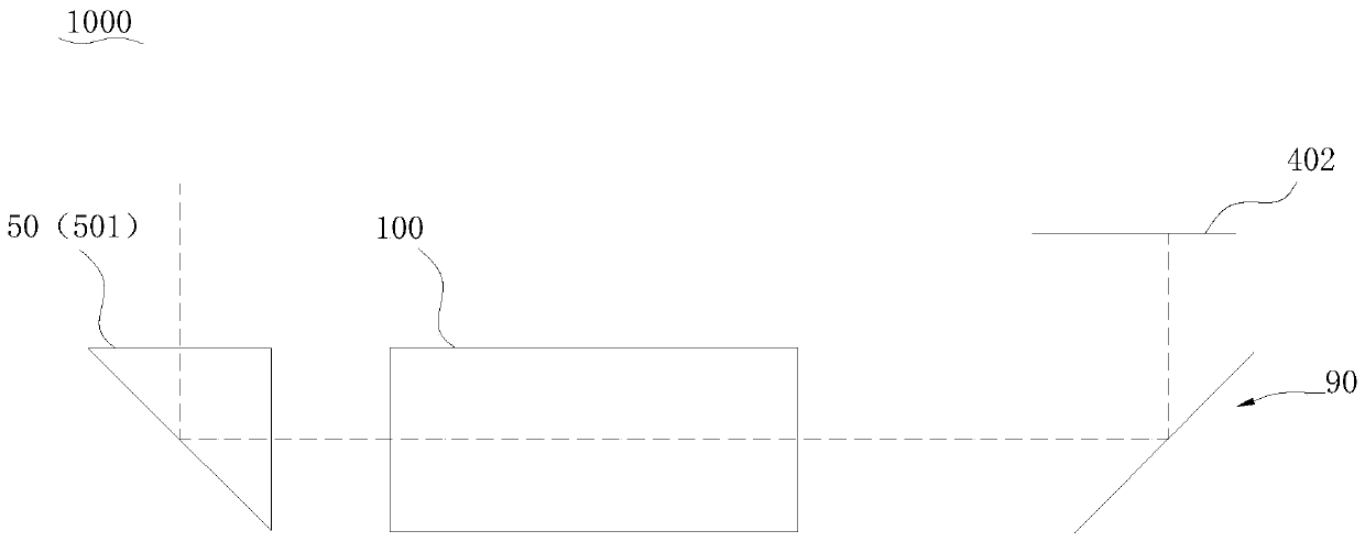
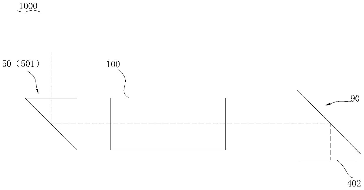
[0023] Embodiments of the present application are described in detail below, examples of which are shown in the drawings, wherein the same or similar reference numerals denote the same or similar elements or elements having the same or similar functions throughout. The embodiments described below by referring to the figures are exemplary, are only for explaining the present application, and should not be construed as limiting the present application.

[0024] In the description of the present application, it should be understood that the terms "center", "longitudinal", "transverse", "length", "width", "thickness", "upper", "lower", "front", " Orientation indicated by rear, left, right, vertical, horizontal, top, bottom, inside, outside, clockwise, counterclockwise, etc. The positional relationship is based on the orientation or positional relationship shown in the drawings, which is only for the convenience of describing the application and simplifying the description, and doe...


PUM


Abstract

The application discloses an optical lens and an electronic device, and the optical lens comprises a first reflector, a lens module, a second reflector and an image sensor, wherein the light incidentfrom the outside is reflected by the first reflector and then enters the lens module, the light emitted from the lens module is incident to the second reflector, the light reflected by the second reflector is converged to the image sensor, and the image sensor is used for converting the focused light into an electrical signal for imaging. The optical lens and the electronic device according to theembodiment of the application fold the optical path between the lens module and the image sensor through the second reflector to reduce the length of the optical lens, which facilitates the placementof components on the main board of the electronic device, facilitates layout, and at the same time, is beneficial to achieve a long focal length optical lens.

Description

technical field [0001] The present application relates to the technical field of optical imaging, in particular to an optical lens and an electronic device. Background technique [0002] Electronic devices such as mobile phones are generally equipped with optical lenses for taking pictures. In order to have better imaging performance, the length of the optical lens is usually longer, which limits the placement of components on the motherboard to a certain extent, making the electronic device bulky and inconvenient to carry. Contents of the invention [0003] Embodiments of the present application provide an optical lens and an electronic device. [0004] The optical lens according to the embodiment of the present application includes a first reflector, a lens module, a second reflector, and an image sensor. The incident light from the outside is reflected by the first reflector and then enters the lens module. The light emitted by the module is incident on the second ref...

Claims


Application Information

Patent Timeline
IPC IPC(8): G02B13/00G03B17/12G03B17/17G03B30/00
CPCG02B13/0065G02B13/007G03B17/12G03B17/17
Inventor 徐青
Owner GUANGDONG OPPO MOBILE TELECOMM CORP LTD
Why Eureka
Try Eureka