
Device for shooting large-area sample on microscope and use method thereof

A microscope, large-area technology, applied in microscopes, optics, instruments, etc., can solve the problems of unable to capture the microstructure of the sample, limit the optical characterization of large-sized samples, and cannot meet the samples larger than centimeter size, etc., to increase the resolution. , the effect of novel representations

Inactive Publication Date: 2020-02-07
TIANJIN UNIV
View PDF10 Cites 1 Cited by
  • Summary
  • Abstract
  • Description
  • Claims
  • Application Information

AI Technical Summary

Problems solved by technology

[0002] The image field of the lowest magnification lens of the current commercial optical polarization microscope objective lens is about 1×1cm2, which cannot directly capture samples larger than centimeters in size, which limits the optical characterization of large-sized samples
For large-sized samples, especially crystal samples, although independent polarizers can be used with commercial digital camera lenses to complete the shooting, the contrast and resolution of the photos are difficult to meet the scientific research requirements, and the microstructure of the samples cannot be captured

Method used


Image

  • Device for shooting large-area sample on microscope and use method thereof
  • Device for shooting large-area sample on microscope and use method thereof

Examples


Embodiment 1

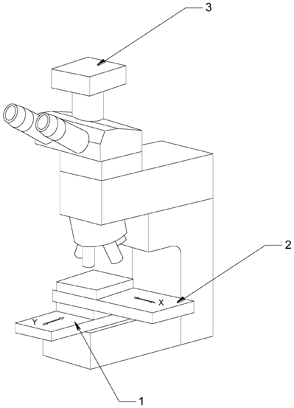
[0026] Refer to the attached figure, a device for photographing large-area samples on a microscope, including a polarized light microscope and a host computer. On the base of the polarized light microscope, two motorized translation stages are arranged orthogonally and stacked together. The base of the light microscope is provided with a first electric translation stage 1 arranged along the Y axis and a second electric translation stage 2 arranged along the X axis. The second electric translation stage 2 is fixedly installed on the slider of the first electric translation stage 1 , And then the slider of the first electric translation table 1 can drive the entire second electric translation table 2 to move along the Y axis, plus the slider of the second electric translation table 2 can move along the X axis, and then the second electric translation table 2 The slider can be adjusted arbitrarily in the plane.

[0027] The slider of the second electric translation stage 2 serves as...

Embodiment 2

[0032] Furthermore, the first electric translation stage 1 and the second electric translation stage 2 both adopt roller bearing electric translation stages driven by a stepping motor, and the upper computer uses LabVIEW software to control the first electric translation stage 1 and the second electric translation stage. The moving step length, moving direction, waiting time of the electric translation stage 2 and the photographing shutter of the CCD image acquisition sensor are triggered.

Embodiment 3

[0034] The method of using the equipment for taking large-area samples on a microscope is as follows:

[0035] Step 1: Place the sample to be photographed on the slider of the second electric translation stage 2;

[0036] Step 2: Select the objective magnification of the polarized light microscope, complete the focus, determine the reasonable imaging range, set the sample moving step, moving direction, waiting time, and the interval time and number of photos on the host computer;

[0037] Step 3: According to the control parameters determined in step 2, the upper computer controls the first electric translation stage 1, the second electric translation stage 2 and the CCD image acquisition sensor to complete the image acquisition of the sample;

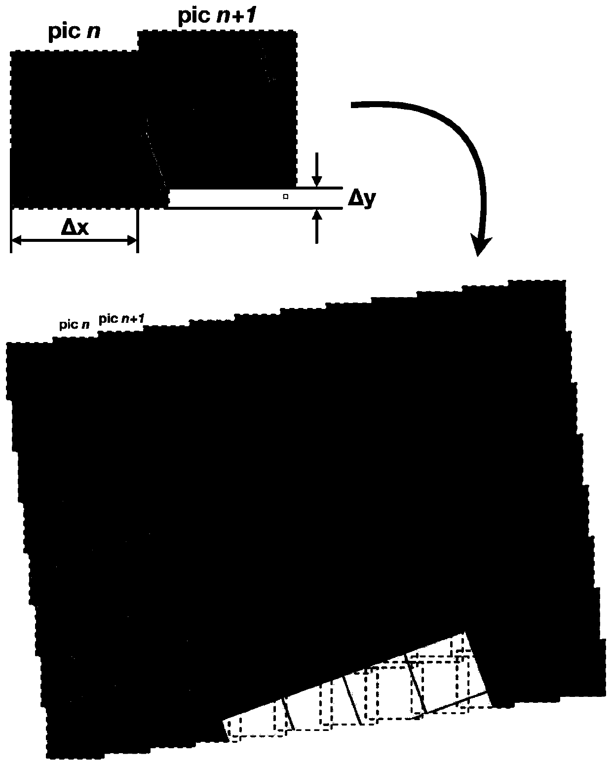
[0038] Step 4: Finally, calibrate the size of the captured photos in the horizontal and vertical directions, input the calibrated offset into the software, read and locate the photo coordinates through LabVIEW, using such figure 2 As shown in...


PUM


Abstract

The invention discloses a device for shooting a large-area sample on a microscope and a use method thereof. Two electric translation platforms which are orthogonally stacked and mounted together are arranged on a base of the microscope, and a sliding block of the electric translation platform located at the upper part is used as a sample placement platform; an image acquisition sensor is arrangedat the top of the microscope and used for shooting the sample and acquiring an image of the sample; the image acquisition sensor of the microscope is connected with an upper computer, the upper computer controls the image acquisition sensor to shoot, and the image acquired by the image acquisition sensor through shooting is transmitted back to the upper computer for splicing processing of subsequent images; the electric translation platforms are connected with the upper computer, and the upper computer controls the two electric translation platforms to move so as to control the shooting position of the sample. The imaging advantage of the optical polarized light microscope can be fully utilized, compared with a digital camera picture, the shooting resolution is increased by hundreds of times, and a breakthrough is brought to the imaging range of an existing microscope.

Description

Technical field [0001] The invention belongs to the technical field of microscopic image acquisition, and specifically relates to a device for photographing a large area sample on a microscope. Background technique [0002] At present, the image field of the lowest magnification lens of commercial optical polarized light microscope objectives is about 1×1cm2, which cannot meet the requirements of directly photographing samples larger than centimeter size, which limits the optical characterization of large-size samples. For large-size samples, especially crystal samples, although an independent polarizer can be used with a commercial digital camera lens to complete the shooting, the contrast and resolution of the photo cannot meet the requirements of scientific research, and the microstructure of the sample cannot be captured. Summary of the invention [0003] The purpose of the present invention is to overcome the shortcomings of the prior art and provide a device for photographin...

Claims


Application Information

Patent Timeline
Patent Type & Authority Applications(China)
IPC IPC(8): G02B21/36
CPCG02B21/362G02B21/365
Inventor 汪涛胡文平张小涛任晓辰耿博文张静席悦牟麒
Owner TIANJIN UNIV
Learn More