Lens system for use with high laser power density scanning system

A technology of laser power and lens system, used in lasers, laser welding equipment, laser parts and other directions, can solve the problems of high lateral chromatic aberration and increased system distortion of the lens system

Inactive Publication Date: 2020-02-07
NEWPORT CORP
View PDF8 Cites 2 Cited by
  • Summary
  • Abstract
  • Description
  • Claims
  • Application Information

AI Technical Summary

Problems solved by technology

As a result, prior optical systems typically suffer from higher absorption that causes temperature variations among the optical components used in the lens system, increasing system distortion
Also, prior art lens systems typically suffer from high lateral chromatic aberration, resulting in undesired variations in spot size and / or shape and variations in processing of the workpiece and / or work surface

Method used


Image

  • Lens system for use with high laser power density scanning system
  • Lens system for use with high laser power density scanning system
  • Lens system for use with high laser power density scanning system

Examples


Embodiment Construction

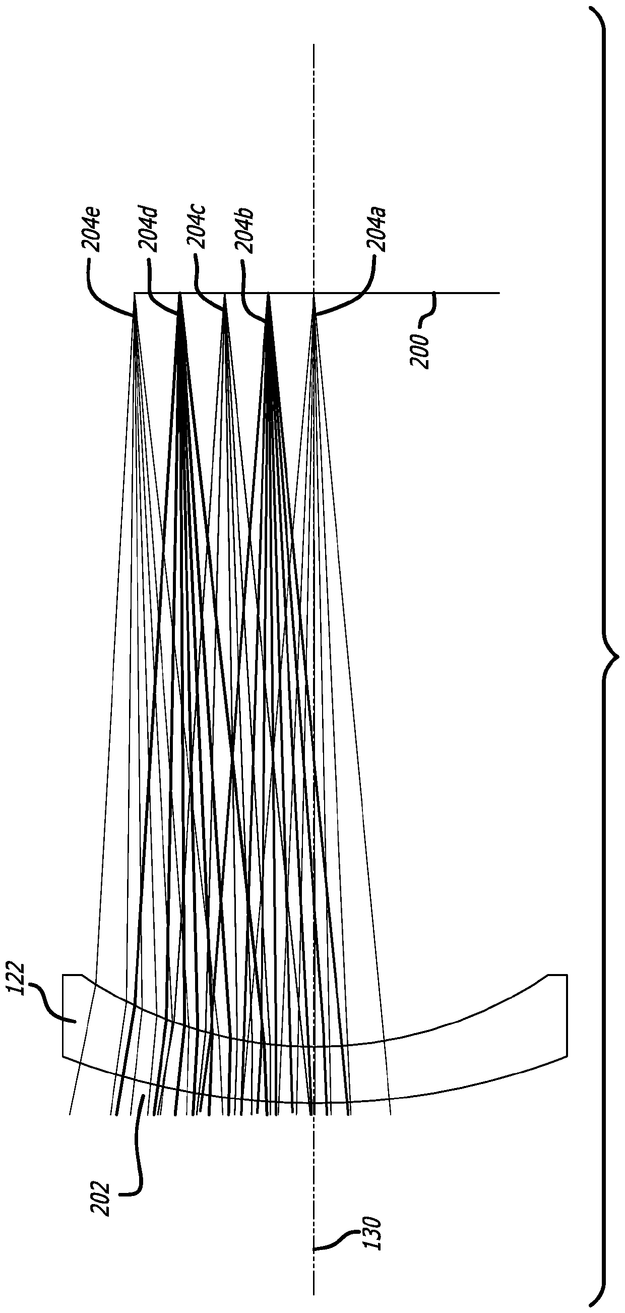
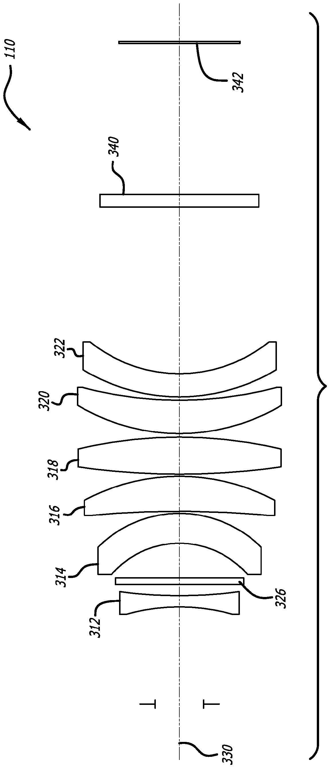
[0024] This application relates to lens systems used in high laser power density scanning systems. More specifically, the lens system may be used in conjunction with a high laser power density scanning system to form one or more features, voids and / or holes in one or more workpieces or surfaces. For example, in one embodiment, the lens systems disclosed herein can be used to form rough features (features having lateral dimensions greater than about 900 μm) in a workpiece. In another embodiment, the lens systems disclosed herein may be used to form features, holes, etc. in a workpiece having lateral dimensions of about 1 μm to about 900 μm. Alternatively, the lens systems disclosed herein may be used to form features, holes, etc. having lateral dimensions of about 5 μm to about 100 μm on the surface of a workpiece. In another embodiment, the lens system disclosed in this application can be used to form features, holes, etc. having lateral dimensions of about 10 μm to about 30 ...


PUM

PropertyMeasurementUnit
sizeaaaaaaaaaa
sizeaaaaaaaaaa
thicknessaaaaaaaaaa

Abstract

A lens system for use with a high laser power density scanning system is disclosed and includes a first lens group having one or more refractive optical elements therein. The first lens group is in communication with at least one high average power laser scanning system and is configured to transmit at least one high average laser power density signal there through. At least a second lens group having one or more refractive optical elements therein is in communication with the laser scanning system via the first lens group. The second lens group is configured to transmit the high average laserpower density signal there through. At least one diffractive optical element may be in communication with at least one of the first lens group and the second lens group and is configured to transmitthe at least one high average laser power density signal there through.

Description

[0001] Cross References to Related Applications [0002] This application claims priority to U.S. Provisional Patent Application Serial No. 62 / 490,409, filed April 26, 2017, entitled "Lens System for Use with High LaserPower Density Scanning System," the entire contents of which are hereby incorporated by reference . Background technique [0003] High laser power density scanning systems are currently used in many applications. For example, high power laser scanning systems are often used in semiconductor manufacturing applications, electronic device manufacturing processes, and similar applications. Typically, high power laser scanning systems include at least one lens system configured to direct laser light to a workpiece and / or work surface. Prior art lens systems used in these scanning systems include a plurality of refractive optical elements configured to condition and direct light energy to a workpiece and / or work surface. [0004] Although prior art lens systems pro...

Claims


Application Information

Patent Timeline
Patent Type & Authority Applications(China)
IPC IPC(8): G02B26/10G02B5/18G02B27/00H01S3/00
CPCB23K26/0648B23K26/0652B23K26/066B23K26/082G02B13/0005G02B13/0055G02B26/101G02B5/1895G02B26/10G02B27/0037G02B27/005H01S3/005G02B5/189G02B9/62G02B13/22G02B27/0031
Inventor R.崔德特D.赫伯格E.阿里奥拉
Owner NEWPORT CORP
Why Eureka
Try Eureka