Material evaporator with liquid level balancing function

A technology of liquid level balance and evaporator, which is applied in the field of heat exchange, can solve the problems of affecting heat exchange effect, large space occupation, long overall length, etc., and achieves the effect of compact structure, small space occupation and low manufacturing cost

Pending Publication Date: 2020-02-11
DEYANG CITY ZHONGJIA IND CO LTD
View PDF1 Cites 0 Cited by
  • Summary
  • Abstract
  • Description
  • Claims
  • Application Information

AI Technical Summary

Problems solved by technology

However, in the actual application process, due to the sequential arrangement of multi-stage heat exchange tube bundles, the overall length is longer and the space occupation is larger
The number of separation boxes is large, resulting in complex structure and high cost
Moreover, the structure in which the condensate flows out through the separation box also easily causes the steam to be discharged together with the condensate, thereby affecting the heat exchange effect

Method used


Image

  • Material evaporator with liquid level balancing function
  • Material evaporator with liquid level balancing function
  • Material evaporator with liquid level balancing function

Examples


Embodiment 1

[0035] This embodiment discloses a material evaporator with a liquid level balance function, including a housing 1, wherein:

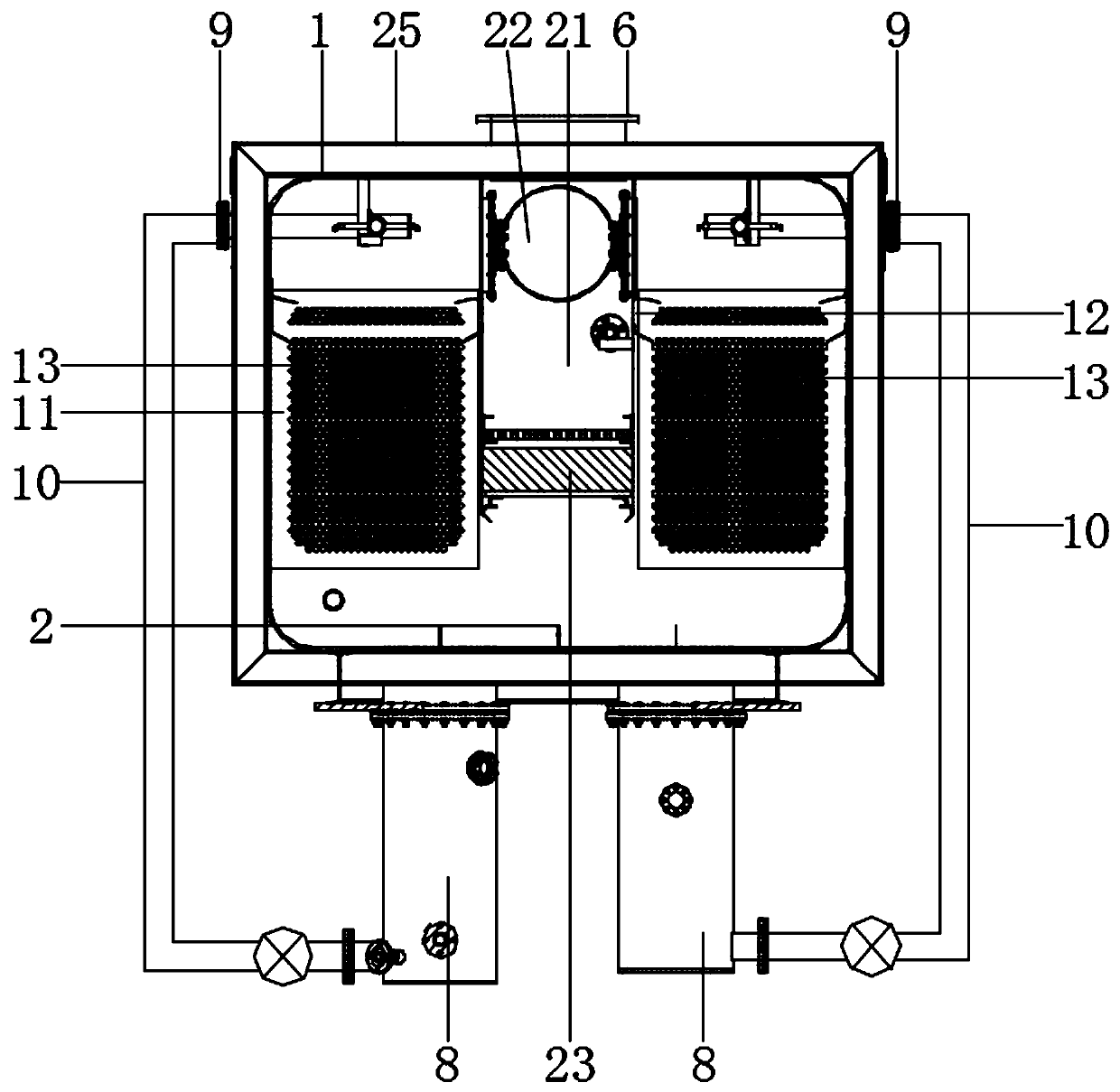
[0036] The casing 1 is fixed with an overflow plate 2 and two sets of horizontal tube falling film evaporators arranged side by side along the axis line, the overflow plate 2 is located at the bottom of the shell 1, and the two sets of horizontal tube falling film evaporators are respectively located 2 on both sides of the top.

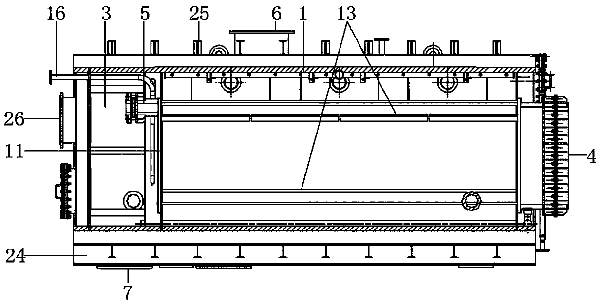
[0037] The horizontal tube falling film evaporation device includes a horizontal tube evaporation mechanism, a steam distribution chamber 3, a steam turning chamber 4 and a U-shaped condensed water discharge mechanism 5, and the steam distribution chamber 3 and the steam turning chamber 4 are respectively located at the steam inlet of the horizontal tube evaporation mechanism. At the end and steam outlet, the U-shaped condensed water discharge mechanism is located in the steam distribution chamber 3, and the U-shaped condensed...

Embodiment 2

[0048] This embodiment discloses a material evaporator with a liquid level balance function, including a housing 1, wherein:

[0049] The casing 1 is fixed with an overflow plate 2 and two sets of horizontal tube falling film evaporators arranged side by side along the axis line, the overflow plate 2 is located at the bottom of the shell 1, and the two sets of horizontal tube falling film evaporators are respectively located 2 on both sides of the top.

[0050] The horizontal tube falling film evaporation device includes a horizontal tube evaporation mechanism, a steam distribution chamber 3, a steam turning chamber 4 and a U-shaped condensed water discharge mechanism 5, and the steam distribution chamber 3 and the steam turning chamber 4 are respectively located at the steam inlet of the horizontal tube evaporation mechanism. At the end and steam outlet, the U-shaped condensed water discharge mechanism is located in the steam distribution chamber 3, and the U-shaped condensed...

Embodiment 3

[0060] This embodiment is basically the same as Embodiment 1 or Embodiment 2, the main difference is:

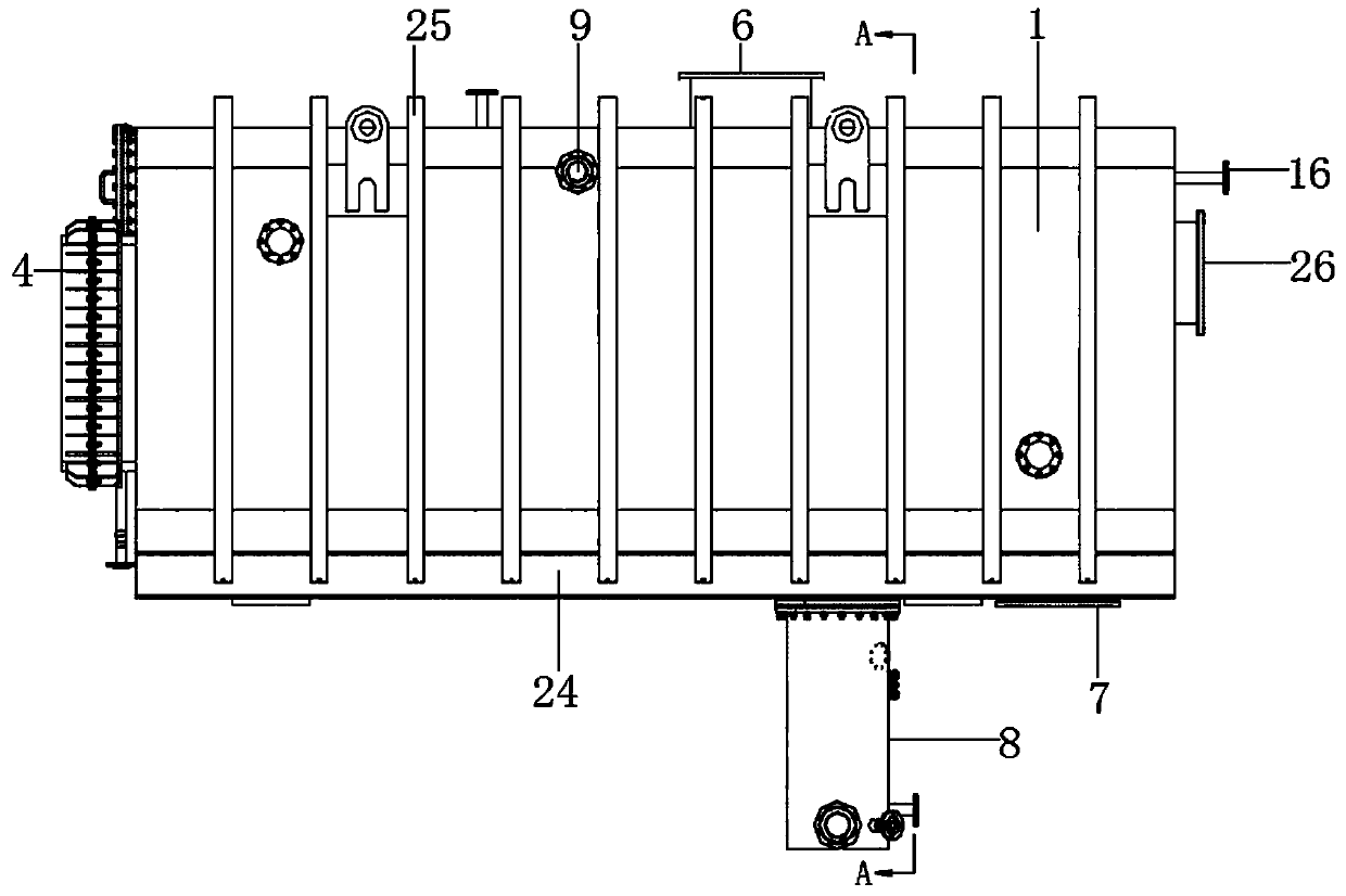
[0061] The shell 1 is a square structure, and the inherent support channel steel 24 is welded symmetrically at the bottom of the shell 1, and there are many reinforcing ribs 25 uniformly distributed on the outer surface of the shell 1, and the reinforcing ribs 25 can be I-shaped steel, L-shaped steel, or H-shaped steel. , I-beam, etc., the reinforcing rib 25 is welded on the shell 1, and the two ends of the reinforcing rib 25 are respectively welded on two supporting channel steels 24.


PUM


Abstract

The invention discloses a material evaporator with a liquid level balancing function. The material evaporator includes a shell, and an overflow plate and two sets of horizontal pipe falling film evaporation devices are fixed in the shell; each horizontal pipe falling film evaporation device comprises a horizontal pipe evaporation mechanism, a steam distribution chamber, a steam rotary chamber anda U-shaped condensate water discharging mechanism, the steam distribution chamber and the steam rotary chamber are respectively located at a steam inlet end and a steam outlet end of the horizontal pipe evaporation mechanism, and the U-shaped condensate water discharging mechanism is located in the steam distribution chamber and used for discharging condensate water and non-condensable gas; a steam outlet is disposed at the top of the shell; a condensate water discharge port and two material circulating barrels are fixed at the bottom of the shell, material circulating feed inlets are respectively arranged on two side walls of the shell, and the two material circulating feed inlets are respectively communicated with the two material circulating barrels through pipelines with pumps. According to the invention, the material evaporator can realize stepped concentration of materials on the premise of small space occupation, and at the same time can keep sealing of steam while discharging condensate water, thus completing evaporation and concentration of materials efficiently.

Description

technical field [0001] The invention relates to the technical field of heat exchange, in particular to a material evaporator with a liquid level balance function. Background technique [0002] The horizontal tube falling film evaporation technology is to add the feed liquid from the upper tube box of the heating chamber of the falling film evaporator, and evenly distribute it to each heat exchange tube through the liquid distribution and film forming device. Membrane flow from top to bottom. During the flow process, the feed liquid exchanges heat with the horizontal tube with steam inside to achieve the purpose of evaporation and concentration. At present, the horizontal tube falling film evaporation technology is widely used in the evaporation and concentration of fluid material water in medicine, food, chemical industry, light industry and other industries due to its good evaporation and concentration effect, as well as sewage treatment in steel, catalyst manufacturing, m...

Claims


Application Information

Patent Timeline
IPC IPC(8): B01D1/04B01D1/22B01D1/30
CPCB01D1/04B01D1/22B01D1/30B01D1/305
Inventor 杨辛洛陶莲莉曲向民陈强
Owner DEYANG CITY ZHONGJIA IND CO LTD
Why Eureka
Try Eureka