Hydraulic stirring device

A mixing device and hydraulic technology, applied in mixers with rotary mixing devices, mixer accessories, transportation and packaging, etc., can solve problems such as large energy consumption, and achieve the effect of reducing energy consumption, saving energy and reducing power

Pending Publication Date: 2020-02-11
徐州市环能生态技术有限公司 +1
View PDF0 Cites 0 Cited by
  • Summary
  • Abstract
  • Description
  • Claims
  • Application Information

AI Technical Summary

Problems solved by technology

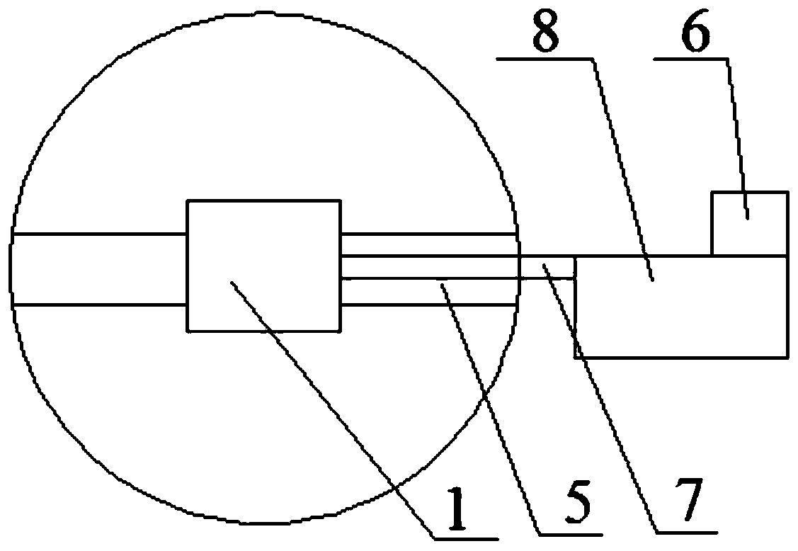
[0004] The purpose of the present invention is to provide a hydraulic stirring device, which solves the problem of large energy consumption in the process of stirring in the prior art

Method used


Image

  • Hydraulic stirring device
  • Hydraulic stirring device
  • Hydraulic stirring device

Examples


Embodiment Construction

[0023] In order to make the purpose, technical solution and advantages of the present invention clearer, the technical solution of the present invention will be described in detail below. Apparently, the described embodiments are only some of the embodiments of the present invention, but not all of them. Based on the embodiments of the present invention, all other implementations obtained by persons of ordinary skill in the art without making creative efforts fall within the protection scope of the present invention.

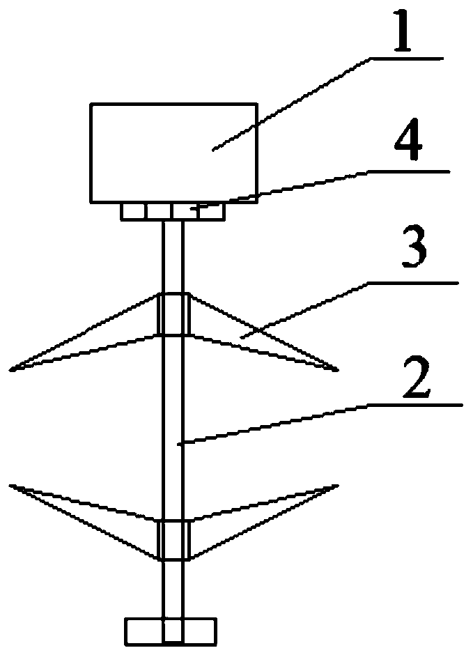
[0024] This specific embodiment provides a hydraulic stirring device, which solves the problem of large energy consumption in the stirring process in the prior art.

[0025] Hereinafter, an embodiment will be described with reference to the drawings. In addition, the examples shown below do not limit the content of the invention described in the claims in any way. In addition, all the contents of the configurations shown in the following embodiments are not li...


PUM


Abstract

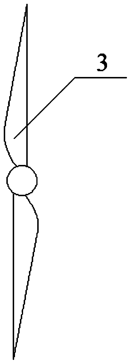
The invention provides a hydraulic stirring device. The device comprises a hydraulic motor, a driving unit for driving the hydraulic motor, and a rotating shaft with one end arranged at the bottom ofa pretreatment tank. The output end of the hydraulic motor is connected to the other end of the rotating shaft, a stirring assembly is arranged on the rotating shaft, and one end of the rotating shaftis arranged at the bottom of the pretreatment tank, thus preventing the rotating shaft equipped with the stirring assembly from going deep into the pretreatment tank, and during installation, the hydraulic motor is connected to the other end of the rotating shaft. The hydraulic motor converts liquid pressure energy provided by the driving unit into mechanical energy with high torque and low rotating speed, namely torque and rotating speed, and then drives the rotating shaft connected to the output end of the hydraulic motor to move, so that the stirring assembly on the rotating shaft can rotate, rotation of the stirring assembly drives the mixing rotation in a biogas slurry tank, and the mixture can be fully mixed. According to the arrangement, the hydraulic motor and the driving unit ofthe hydraulic motor are adopted for cooperation, the consumed power is reduced, the energy consumption is lowered, and the energy is saved.

Description

technical field [0001] The invention relates to the technical field of stirring, in particular to a hydraulic stirring device. Background technique [0002] At present, biogas has been widely used as an environmentally friendly energy source, especially in circular agriculture, especially in circular agriculture. Animal manure in the breeding process and straw in planting As the main source of biogas raw materials, the produced biogas can meet the needs of cooking and basic living, and the waste liquid extracted from the biogas tank can be used as fertilizer to provide nutrition for crops. The entire biogas digester plays a vital role in the entire circular agriculture, but in a high-concentration mixture, stirring the mixture is laborious. The existing stirring device uses a combination of a motor and a deceleration to drive the stirring parts to the mixture. Stirring is carried out, but in the process of stirring, the power consumed by the operation of the motor is relati...

Claims


Application Information

Patent Timeline
IPC IPC(8): B01F7/00B01F15/00
CPCB01F27/112B01F27/191B01F35/32045
Inventor 杜静程学顺奚永兰苗晓胡传杰
Owner 徐州市环能生态技术有限公司
Why Eureka
Try Eureka