Supercharge Your Innovation With Domain-Expert AI Agents!

Bridge-building mixed elevated railway station structure adopting energy dissipation connection

A hybrid, building structure technology, applied in building components, bridges, earthquake-proof and other directions, can solve the problems of inflexible plane layout of station building structure, difficult facility layout, occupying a lot of land, etc., to achieve flexible facility layout and avoid displacement response. Excessive, the effect of improving the bearing capacity

Pending Publication Date: 2020-02-11
TIANJIN UNIV
View PDF0 Cites 4 Cited by
  • Summary
  • Abstract
  • Description
  • Claims
  • Application Information

AI Technical Summary

Problems solved by technology

Although there are advantages such as clear structural force transmission path, simple force bearing, uneven foundation settlement, little impact of station vibration and noise on the surrounding environment, and easy to deal with interface problems in the same section, the large cross-section pier on the station hall floor not only causes The plane layout of the station building structure is inflexible. It is difficult to arrange station equipment and facilities such as air-conditioning equipment, escalators, and barrier-free elevators inside the station building structure. Moreover, the building part of the station building and the viaduct part are independent, occupying a lot of land and costing the project higher

Method used


Image

  • Bridge-building mixed elevated railway station structure adopting energy dissipation connection
  • Bridge-building mixed elevated railway station structure adopting energy dissipation connection
  • Bridge-building mixed elevated railway station structure adopting energy dissipation connection

Examples


Embodiment Construction

[0023] The present invention will be described in detail below in conjunction with the accompanying drawings and specific embodiments.

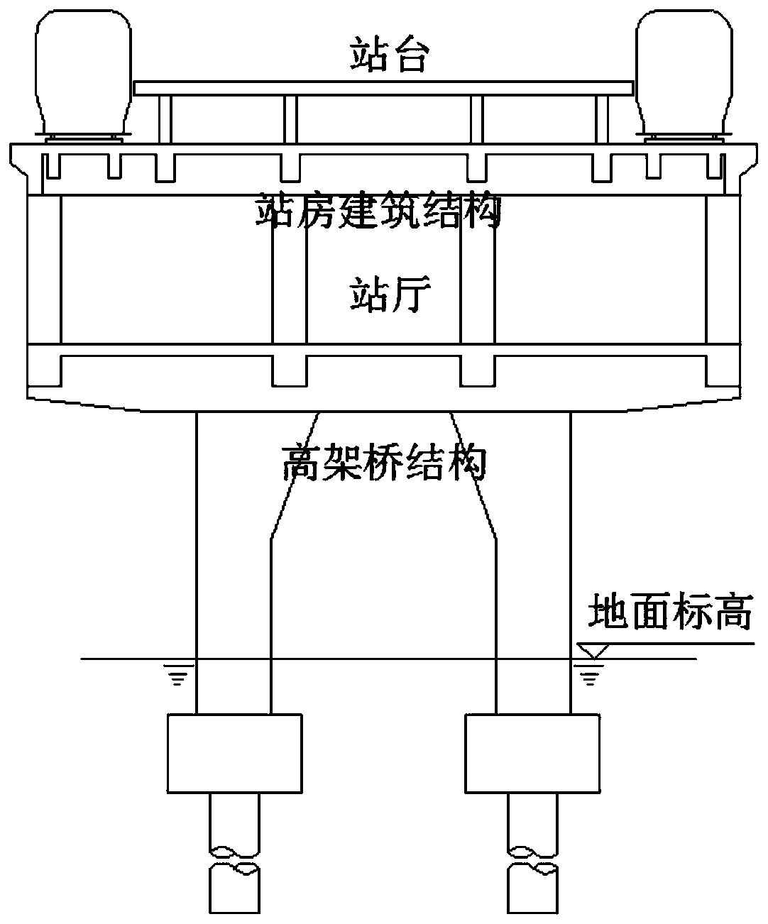
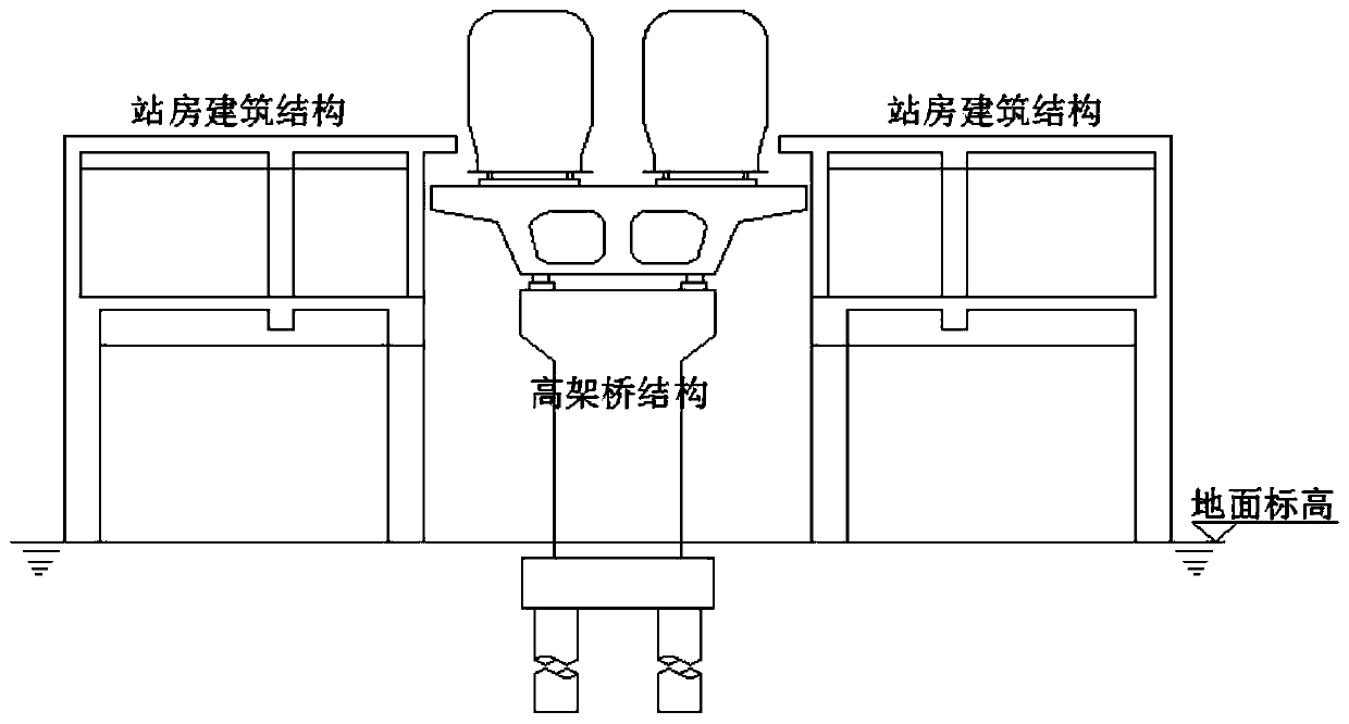
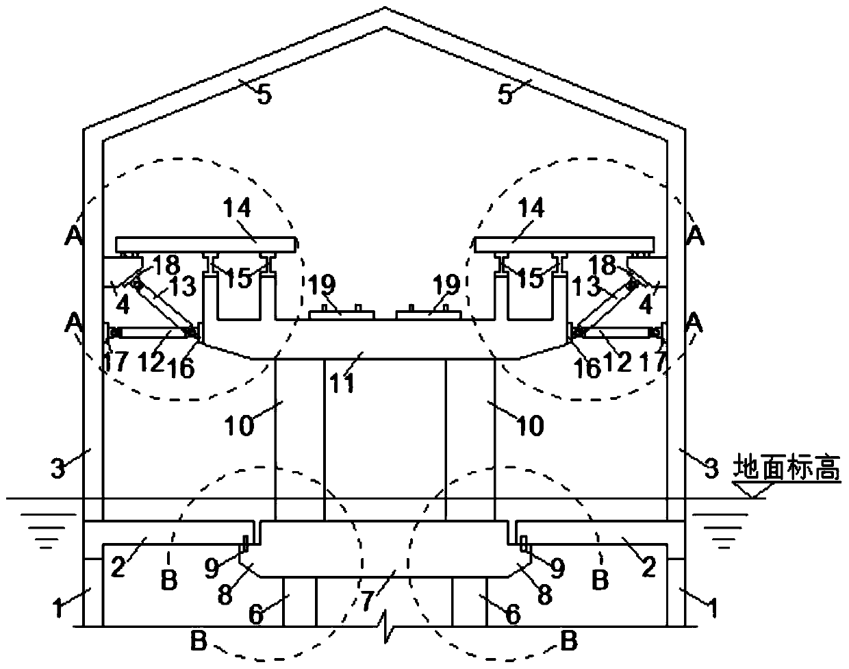
[0024] Such as Figure 3 ~ Figure 7 As shown, a bridge construction hybrid elevated station structure adopting energy dissipation and shock absorption connection of the present invention includes a station building structure and a viaduct structure.

[0025] Described viaduct structure comprises the left and right two rows of viaduct piles 6 that drive into the ground at the viaduct structure place of setting, at the top of every two viaduct piles 6 that are arranged corresponding to each other, a viaduct foundation beam 7 is respectively fixed along the lateral support, On the left and right sides of each viaduct foundation beam 7, an L-shaped support platform is respectively arranged, and on the L-shaped support platform described on each side, the steel bars 9 are pre-embedded respectively along the vertical direction, and on the top of ea...


PUM


Abstract

The invention discloses a bridge-building mixed elevated railway station structure adopting energy dissipation connection. The bridge-building mixed elevated railway station structure adopting the energy dissipation connection is composed of a station building structure, an elevated bridge structure, an energy dissipation damper, a profile steel connection piece and the like. The bridge-building mixed elevated railway station structure adopting the energy dissipation connection realizes connection of the station building structure and the elevated bridge structure through the energy dissipation damper and the profile steel connection piece. The bridge-building mixed elevated railway station structure adopting the energy dissipation connection not only has the advantages of being good in shake deformation resisting ability, and capable of enabling the energy dissipation damper and the profile steel connection piece to synergistically bear force, fully develop respective advantages, provide additional rigidity and be simple and reasonable in respective structure, but also can decrease the occupied area when compared with a traditional bridge-building separated elevated railway station, can decrease the sectional dimension of a beam column member of the elevated bridge structure when compared with a traditional bridge-building combined elevated railway station, then shortens the construction period, reduces construction cost, and has good popularization prospects.

Description

technical field [0001] The invention relates to a bridge-building hybrid elevated station structure, in particular to a bridge-building hybrid elevated station structure that adopts energy-dissipating and shock-absorbing connections. Background technique [0002] According to the relationship between the elevated station building and the viaduct part, traditional elevated stations are mainly divided into two types: "separation of bridge construction" and "integration of bridge construction". [0003] The "bridge-build-in-one" type of traditional elevated stations, such as figure 1 As shown, the building structure is erected on the viaduct structure. The bridge cover beams, pier columns, and foundations are shared by the bridge structure and the building structure. The horizontal frame of the bridge is integrally poured through the vertical building structure beams and slabs to form a space frame system. Although the structural integrity and stability are good, the station b...

Claims


Application Information

Patent Timeline
IPC IPC(8): E01F1/00E01D2/04E04B1/98E04H9/02
CPCE01F1/00E01D2/04E04B1/98E04H9/021
Inventor 罗云标陈跃波李忠献刘中宪
Owner TIANJIN UNIV
Features
  • R&D
  • Intellectual Property
  • Life Sciences
  • Materials
  • Tech Scout
  • Unparalleled Data Quality
  • Higher Quality Content
  • 60% Fewer Hallucinations
Learn More