Defect detection device and method

A defect detection and defect probability technology, applied in the field of computer vision, can solve the problems of low detection efficiency, many misjudgments and missed judgments, and low defect detection accuracy, so as to improve efficiency and reduce misjudgments and missed judgments.

Active Publication Date: 2020-02-11
汪科道
View PDF6 Cites 1 Cited by
  • Summary
  • Abstract
  • Description
  • Claims
  • Application Information

AI Technical Summary

Problems solved by technology

The customization characteristics of non-standardized hardware make its application scenarios have great limitations, and it is difficult to adapt to the detection requirements of various objects
[0003] Defect detection based on traditional vision is extremely dependent on software engineers who write templates or features. Whenever a new defect appears, software engineers need to manually update templates or features, which is less adaptable to new defects, and When using artificially written templates or features for defect detection, it is difficult to detect random defects (such as scratches), and it is also difficult to correctly identify complex material surfaces (such as metal turning surfaces), which is prone to missed and misjudged. Lead to lower accuracy of defect detection
[0004] In addition, based on traditional vision-based defect detection, the trajectory of capturing images of objects is fixed. If an object needs to be inspected in an all-round way, a large number of image capturing times and time are required, and the detection efficiency is low. When multiple images are obtained to determine object defects, each image is judged individually, and there are many misjudgments and missed judgments

Method used


Image

  • Defect detection device and method
  • Defect detection device and method
  • Defect detection device and method

Examples


Embodiment Construction

[0054] The following will clearly and completely describe the technical solutions in the embodiments of the present invention with reference to the accompanying drawings in the embodiments of the present invention. Obviously, the described embodiments are only some, not all, embodiments of the present invention. Based on the embodiments of the present invention, all other embodiments obtained by those skilled in the art without creative efforts fall within the protection scope of the present invention.

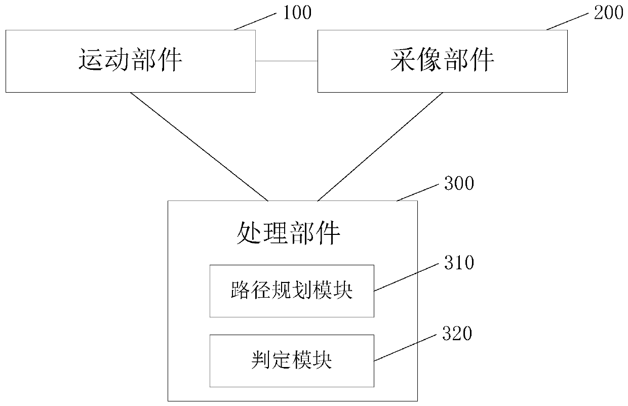
[0055] The defect detection device in the embodiment of the present invention can detect the detection object in all directions and from multiple angles to find out whether there is a defect in it. It can be used for defect detection of various products produced by production enterprises, and can also be used for product integrators. Defect detection of purchased various products (such as components) can also be used in other scenarios, and the present invention does not limit ...


PUM


Abstract

The invention relates to a defect detection device and method. The device comprises a moving part, an image collection part, and a processing part, the processing part is connected with the moving part and the image collection part, and the processing part comprises: a path planning module which is used for determining a plurality of first image collection positions according to all image collection positions of a detection object and a preset first sampling proportion, determining a first defect probability according to the first detection image of each first image acquisition position, establishing a probability matrix according to the first defect probability and a preset defect probability, splitting the probability matrix into a plurality of sub-matrixes, and determining a second defect probability of a local area corresponding to each sub-matrix; and a determination module used for determining the maximum value of the second defect probability as a third defect probability, determining that the detection object has defects when the third defect probability is greater than or equal to a defect probability threshold, and otherwise, determining that the detection object has no defects. According to the embodiment of the invention, the defect detection efficiency and the detection result accuracy can be improved.

Description

technical field [0001] The invention relates to the field of computer vision, in particular to a defect detection device and method. Background technique [0002] Currently, defect detection on objects (such as various metal castings) is mainly based on traditional vision, for example, object defect detection by template matching or human-written features. The hardware used in this method is mainly non-standardized hardware, that is, in order to capture objects of different geometric shapes and capture images of different defects during defect detection, it is necessary to customize tooling, fixtures, image acquisition methods, and lighting methods. Even customize the overall mechanical structure of the detection device, etc. The customization characteristics of non-standardized hardware make its application scenarios have great limitations, and it is difficult to adapt to the detection requirements of various objects. [0003] Defect detection based on traditional vision ...

Claims


Application Information

Patent Timeline
IPC IPC(8): G01N21/88G06V10/24G06V10/764
CPCG01N21/8851G01N2021/8887G01N2201/1296G06T7/0004G06T2207/20084G06N3/08G06V10/24G06V2201/06G06V10/764G06N3/048G06N3/045G06F18/259G06T7/0006G06F18/2415G06N7/01
Inventor 汪科道
Owner 汪科道
Why Eureka
Try Eureka