
Thermoelectric device

A technology of thermoelectric devices and thermoelectric elements, which is applied in the manufacture/processing of thermoelectric device parts, circuits, and thermoelectric devices, etc., can solve problems such as mechanical damage of thermoelectric elements, and achieve the effect of simple electrical contact

Pending Publication Date: 2020-02-11
MAHLE INT GMBH
View PDF0 Cites 0 Cited by
  • Summary
  • Abstract
  • Description
  • Claims
  • Application Information

AI Technical Summary

Problems solved by technology

[0005] As a result, it has often proved problematic that thermoelectric elements designed in this way are susceptible to mechanical damage

Method used


Image

  • Thermoelectric device
  • Thermoelectric device
  • Thermoelectric device

Examples


Embodiment Construction

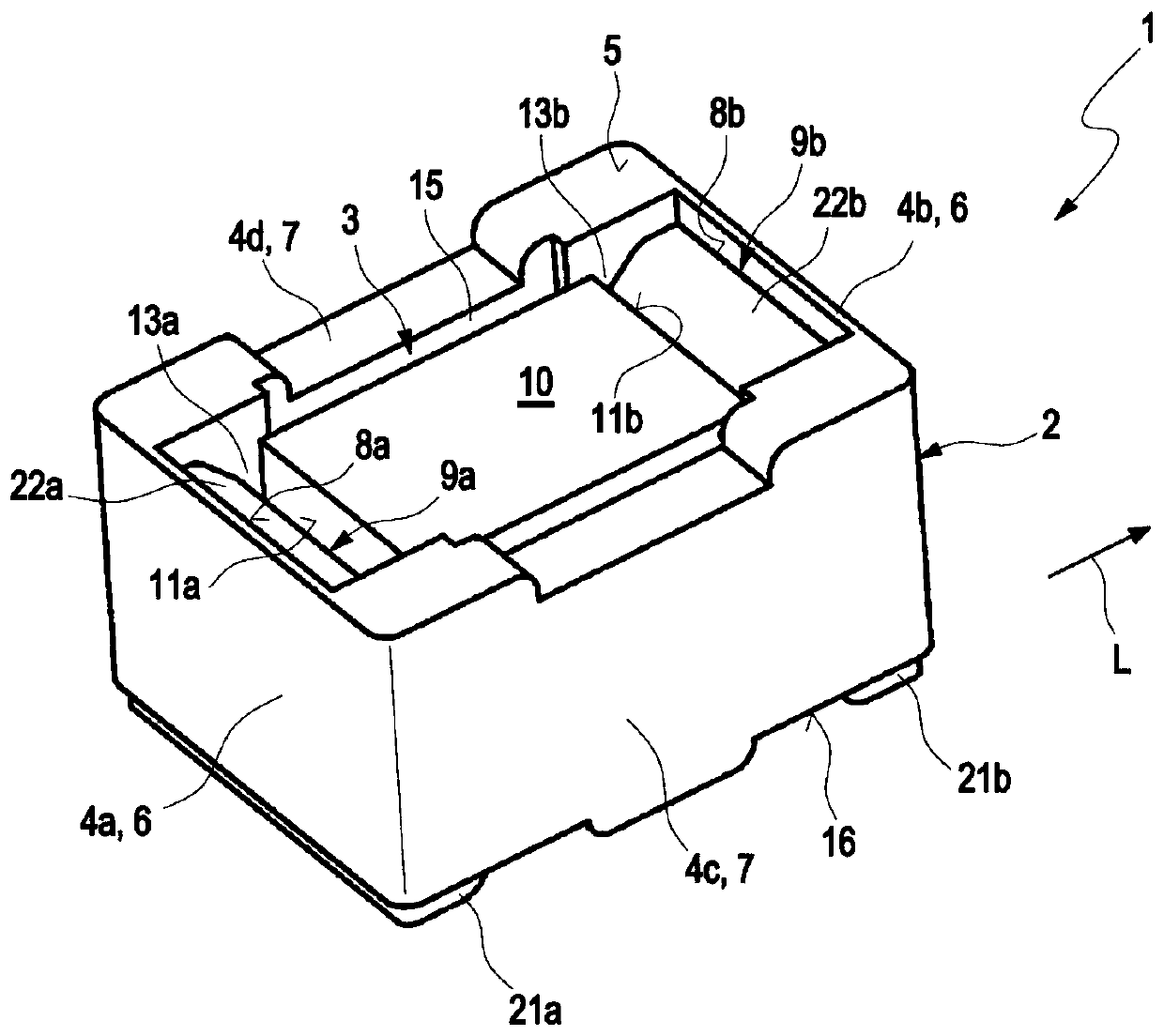
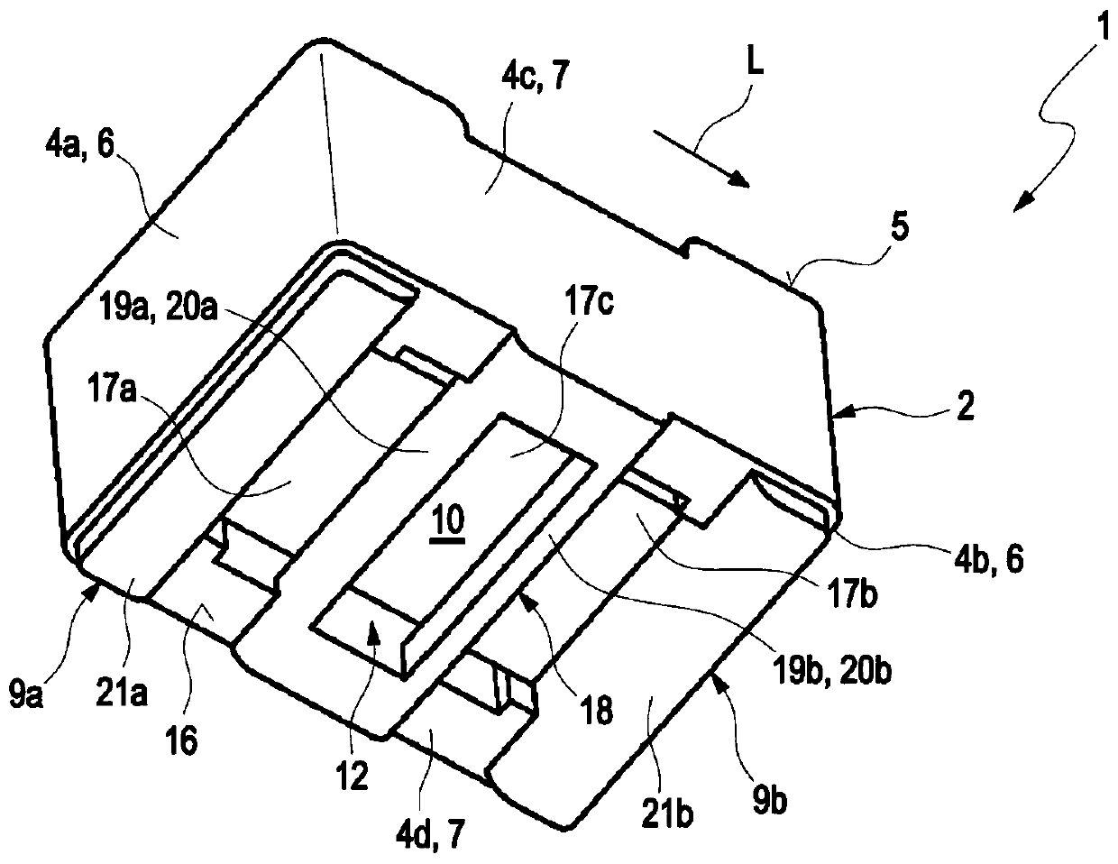
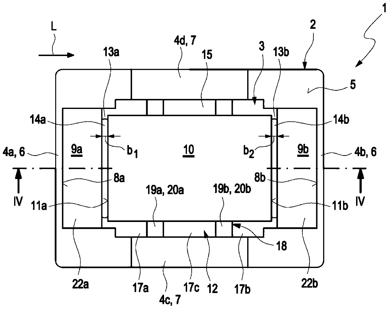
[0039] figure 1 and 2 An example of a thermoelectric device 1 according to the invention is shown in different perspective views. The thermoelectric device 1 comprises an open housing 2 made of an electrically insulating material such as plastic. The housing 2 delimits an inner space 3 of the housing. The casing 2 includes a first side wall 4a and a second side wall 4b opposite to the first side wall 4a. The two side walls 4a, 4b are in turn connected to each other with a third side wall 4c and a fourth side wall 4d, which are also positioned opposite each other. In a top view of the top side 5 of the housing 2, the first side wall 4a and the second side wall 4b form the narrow side 6, and the third side wall 4c and the fourth side wall 4d form the longitudinal side 7 of the housing 2, which In plan view the top side 5 of the housing 2 has a rectangular geometry. In a special case (not shown), in particular square geometries are conceivable. However, other housing geomet...


PUM


Abstract

The present invention relates to a thermoelectric device (1) which may include a housing (2) made of a plastic, which may partially limit an interior space (3) and which may include a first side wall(4a) and a second side wall (4b) lying opposite to the first side wall, and a thermoelectric element (10) made of a thermoelectrically active material arranged in the interior space. The first electrical connection element (9) may be arranged on an inner side (8a) of the first side wall, and a second electrical connection element (9b) may be arranged on an inner side (8b) of the second side wall.The first electrical connection element may be connected in a substance-to-substance manner to a first front side (11a) of the thermoelectric element facing the first side wall, and the second electrical connection element may be connected to a second front side (11b) of the thermoelectric element facing the second side wall.

Description

technical field [0001] The present invention relates to thermoelectric devices. The invention also relates to a thermoelectric assembly having such a thermoelectric device. Background technique [0002] A thermoelectric element of a thermoelectric device includes a thermoelectrically active semiconductor material that converts a temperature difference into a potential difference, ie, voltage, and vice versa. In this way, heat flow can be converted into electric current and vice versa. Thermoelectric elements are based on the Peltier effect when converting electrical energy into heat and the Seebeck effect when converting heat into electrical energy. Within a thermoelectric module, p-doped and n-doped thermoelectric elements are interconnected with each other. A plurality of such thermoelectric elements is usually connected to a thermoelectric generator, which can generate an electric current from a temperature difference in combination with a corresponding heat flow. If ...

Claims


Application Information

Patent Timeline
IPC IPC(8): H01L35/10H01L35/32H01M10/6572F02G5/02H02N11/00
CPCH01M10/6572F02G5/02H02N11/002H10N10/82H10N10/17Y02E60/10H10N10/817H10N10/01
Inventor J·格伦沃尔德S·霍庇A·凯姆莱J·朔纳
Owner MAHLE INT GMBH
Learn More