
Dynamic threshold timing circuit, laser radar and method for acquiring time information

A dynamic threshold and timing circuit technology, applied in the field of circuits, can solve the problems of high power consumption and heat generation of the circuit, unfavorable operation of the device heat generation system, etc., and achieve the effects of dynamic calibration, low power consumption, and reduced amplitude requirements.

Active Publication Date: 2020-02-11
HESAI TECH CO LTD
View PDF5 Cites 10 Cited by
  • Summary
  • Abstract
  • Description
  • Claims
  • Application Information

AI Technical Summary

Problems solved by technology

The increase of circuit power consumption usually leads to high heat generation. For lidar applications, due to the accumulation of a large number of devices in a small space, the increase in device heat generation is extremely detrimental to system operation.

Method used


Image

  • Dynamic threshold timing circuit, laser radar and method for acquiring time information
  • Dynamic threshold timing circuit, laser radar and method for acquiring time information
  • Dynamic threshold timing circuit, laser radar and method for acquiring time information

Examples


Embodiment Construction

[0060] In the following, only some exemplary embodiments are briefly described. As those skilled in the art would realize, the described embodiments may be modified in various different ways, all without departing from the spirit or scope of the present invention. Accordingly, the drawings and descriptions are to be regarded as illustrative in nature and not restrictive.

[0061] In describing the present invention, it is to be understood that the terms "center", "longitudinal", "transverse", "length", "width", "thickness", "upper", "lower", "front", " Back", "Left", "Right", "Straight", "Horizontal", "Top", "Bottom", "Inner", "Outer", "Clockwise", "Counterclockwise", etc. or The positional relationship is based on the orientation or positional relationship shown in the drawings, which is only for the convenience of describing the present invention and simplifying the description, rather than indicating or implying that the referred device or element must have a specific orie...


PUM

PropertyMeasurementUnit
Sampling frequencyaaaaaaaaaa

Abstract

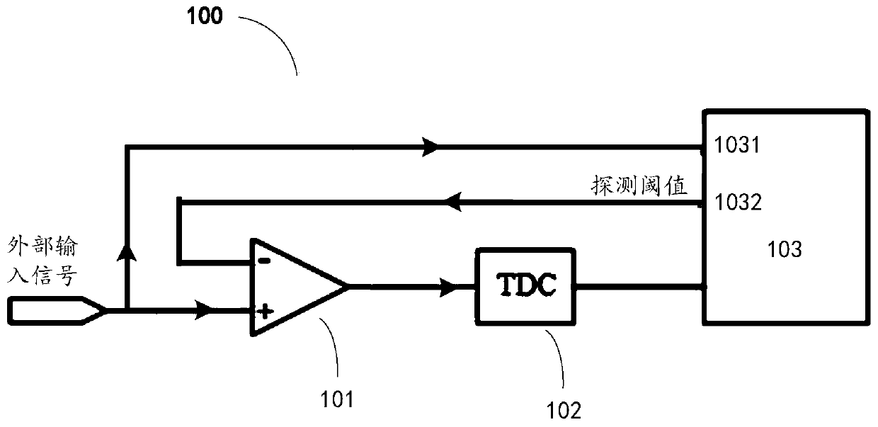
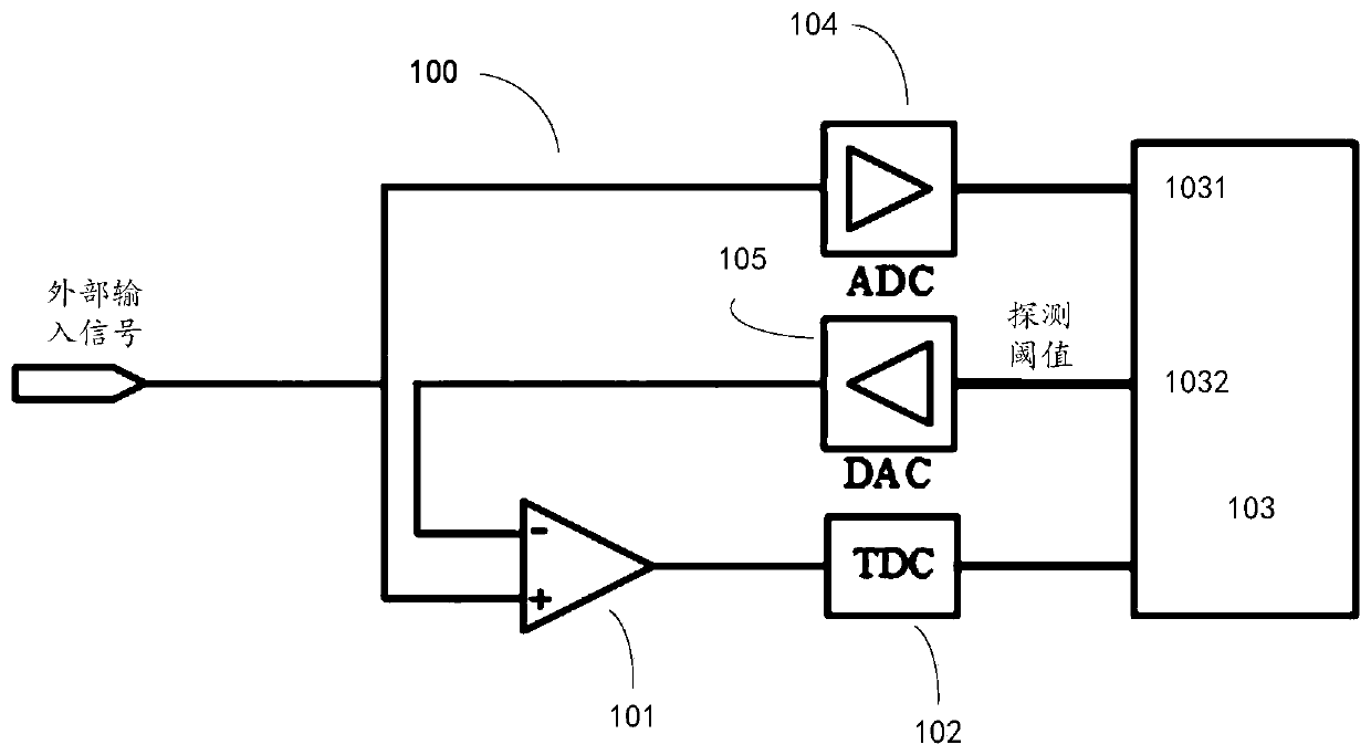
The present invention relates to a dynamic threshold timing circuit, comprising: a comparator having a first input terminal capable of receiving an external input signal, a second input terminal capable of receiving a detection threshold, and an output terminal; a time-to-digital converter which is coupled with the output end of the comparator so as to acquire time information of an output signalof the comparator; a controller which is configured to be capable of receiving the external input signal, generating the detection threshold value according to the external input signal and providingthe detection threshold value for the second input end of the comparator, wherein the detection threshold value is related to noise in the external input signal.

Description

technical field [0001] The present invention generally relates to the field of circuit technology, and in particular to a dynamic threshold timing circuit, a laser radar including the same, and a method for collecting time information of an external input signal. Background technique [0002] A Time-to-Digital Converter (TDC) is a measurement device or device that digitizes time information, and a timing circuit is a circuit that extracts time information from an analog signal to be measured. An analog signal carrying time information cannot be directly used as the input of TDC. It needs to extract the time information in the signal by a timing circuit, output a time signal carrying time information, and send it to TDC. Time information is usually carried by the signal edge of the level transition. The output of TDC is only the digital quantization result of the measured time signal, and other information such as amplitude and waveform can not be obtained except time inform...

Claims


Application Information

Patent Timeline
IPC IPC(8): H03M1/12
CPCH03M1/124
Inventor 王力威向少卿
Owner HESAI TECH CO LTD
Learn More