
Method and microscopy system for recording an image

An image and objective lens technology used in the field of microscope systems

Active Publication Date: 2020-02-11
EUROIMMUN MEDIZINISCHE LABORDIAGNOSTIKA
View PDF5 Cites 4 Cited by
  • Summary
  • Abstract
  • Description
  • Claims
  • Application Information

AI Technical Summary

Problems solved by technology

[0007] Therefore, the methods and systems of the prior art cannot ensure fast and reliable focusing of samples in microscopes, especially fluorescence microscopes, under all conditions

Method used


Image

  • Method and microscopy system for recording an image
  • Method and microscopy system for recording an image
  • Method and microscopy system for recording an image

Examples


Embodiment Construction

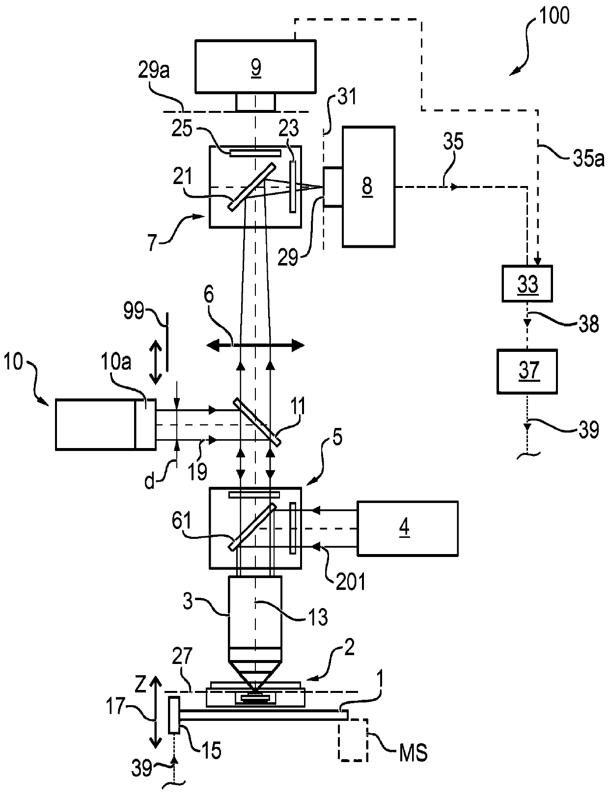
[0064] exist figure 1 The microscope system 100 , illustrated in a schematic side sectional view in FIG. 2 , comprises an objective 3 which is movable relative to the sample region 2 along its optical axis 13 . In general the objective 3 and the sample area 2 are movable relative to each other along the optical axis 13 . For this purpose, a drive mechanism 15 is provided which is configured to move the microscope stage 1 (or the objective lens 3) in the direction of the arrow 17 (i.e. in the Z direction or in the vertical direction) while the objective lens 3 is fixed, or While the stage is fixed, the objective lens is moved. Microscope system 100 also includes a laser 10 which is designed to generate a laser beam 19 which is directed via objective 3 onto sample region 2 . The laser light source or laser 10 comprises collimation optics 10a by means of which the laser beam can be shaped into a parallel collimated beam of radiation. Preferably, the collimating optics 10a are ...


PUM


Abstract

A method and a microscopy system for recording an image of a sample region are provided, including: directing a laser beam onto the sample region containing at least one interface by means of at leastone objective lens, wherein the objective lens brings about an imaging of the laser beam on a focusing point which lies on the optical axis of the objective lens or on an axis lying parallel theretoand which further lies in a focusing plane; displacing the objective lens and the sample region with respect to one another in relative fashion along the optical axis of the objective lens to a plurality of different relative displacement positions; capturing a plurality of intensity values of the laser beam for a respective relative displacement position, said laser beam being reflected at the interface and passing through the objective lens, said intensity values being detected by pixels of a two-dimensional portion of a detection surface of a microscope camera; determining a respective highest intensity value for a respective displacement position; determining a curve of the highest intensity values; determining a reference relative displacement position from at least one maximum of thecurve; capturing at least one image of the sample region at the reference relative displacement position.

Description

technical field [0001] The invention relates to a method for recording an image of a sample region, in particular for recording a fluorescence image, and also to a microscope system for recording an image of a sample region. Background technique [0002] DE 10 2008 015 885 A1 describes a method for automatic focusing of an optical device, in which a measuring light source and an objective lens are provided for imaging a substantially parallel beam of rays emanating from the measuring light source onto an observation object to produce a reflected image , wherein an evaluation and adjustment unit is also provided, which is suitable for determining the focus position from the reflected image and for positioning the objective lens. Here, images are recorded with concentric rings whose diameter changes depending on the distance to the correct focus position. [0003] WO 2016 / 133787 A1 discloses a method and a system for automatically focusing a microscope on a sample and for tak...

Claims


Application Information

Patent Timeline
IPC IPC(8): G02B21/24
CPCG02B21/245G02B21/0032G02B21/006G02B21/008G02B21/02G02B21/361G02B21/367
Inventor H·潘恩霍夫M·哈根-埃格特M·莫林M·米勒T·J·祖姆普夫
Owner EUROIMMUN MEDIZINISCHE LABORDIAGNOSTIKA
Learn More