
Automatic quartz plate loading system

A technology of automatic feeding and crystal wafers, which is applied in the direction of conveyor objects, transportation and packaging, etc., can solve problems such as easy deviation of the placement position of quartz crystals, inability to realize automatic feeding of crystal wafers, damage to crystal wafers to be processed, etc., to achieve Simple structure, satisfying automatic production and improving production efficiency

Pending Publication Date: 2020-02-14
北京石晶光电科技股份有限公司
View PDF0 Cites 2 Cited by
  • Summary
  • Abstract
  • Description
  • Claims
  • Application Information

AI Technical Summary

Problems solved by technology

[0002] The crystal wafer needs to be loaded during the production and processing process. The crystal wafer needs to be placed on the predetermined loading position of the material table and then transported to the processing site of the next processing process. The traditional feeding method is to manually place a piece of The crystal wafer is sent to the quartz crystal fixture, and then placed on the material table through the fixture, the crystal wafer placed on the material table is absorbed by the suction head on the transfer device, and then transported to the next processing site by the transfer device Waiting for the next step of processing, the transfer device needs to continuously adjust the effective distance of the suction head according to the product specifications during the process of transporting the crystal wafer, which is more troublesome to operate
The traditional feeding method consumes a lot of manpower, is slow, and is easy to damage the crystal wafer to be processed, and the position of the quartz crystal is prone to deviation, which affects the processing of the crystal wafer in the next process and cannot realize automatic feeding of the crystal wafer. So there is an urgent need to design a system that can automatically load crystal wafers

Method used


Image

  • Automatic quartz plate loading system
  • Automatic quartz plate loading system

Examples


Embodiment Construction

[0020] For further elaborating the technical means and effects that the present invention adopts for reaching the intended purpose of the invention, below in conjunction with accompanying drawing and preferred embodiment, to its specific implementation, structure, Features and their functions are described in detail below.

[0021] In describing the present invention, it is to be understood that the terms "center", "upper", "lower", "front", "rear", "left", "right", "vertical", "horizontal", The orientation or positional relationship indicated by "top", "bottom", etc. are based on the orientation or positional relationship shown in the drawings, and are only for the convenience of describing the present invention and simplifying the description, rather than indicating or implying that the referred device or element must be Having a particular orientation, being constructed and operating in a particular orientation, and therefore not to be construed as limiting the invention. ...


PUM


Abstract

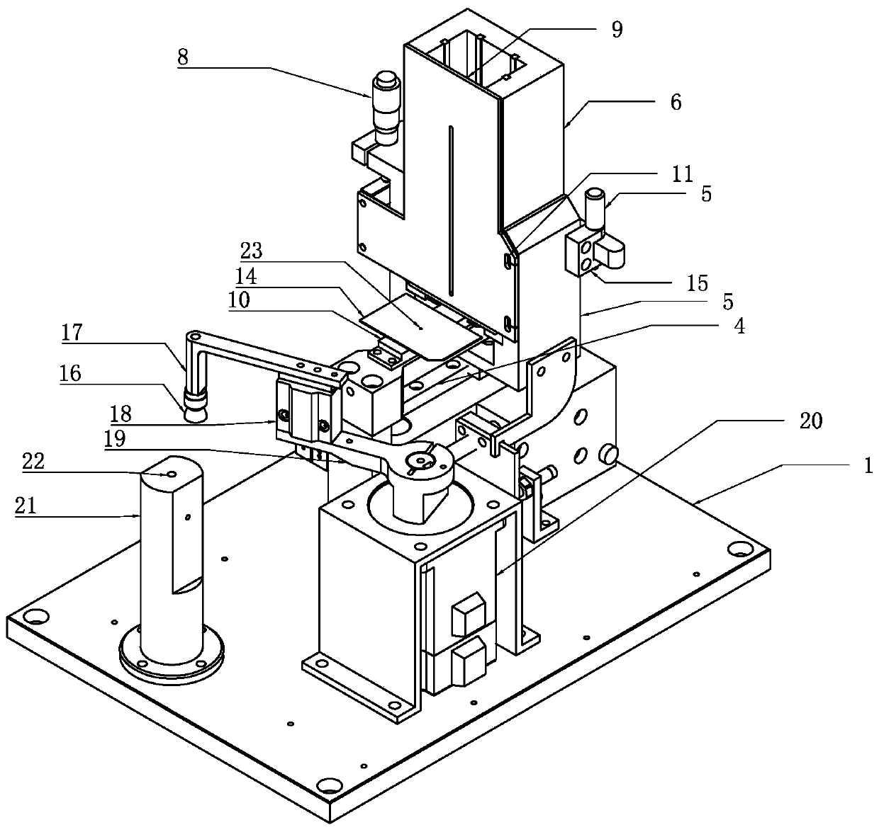
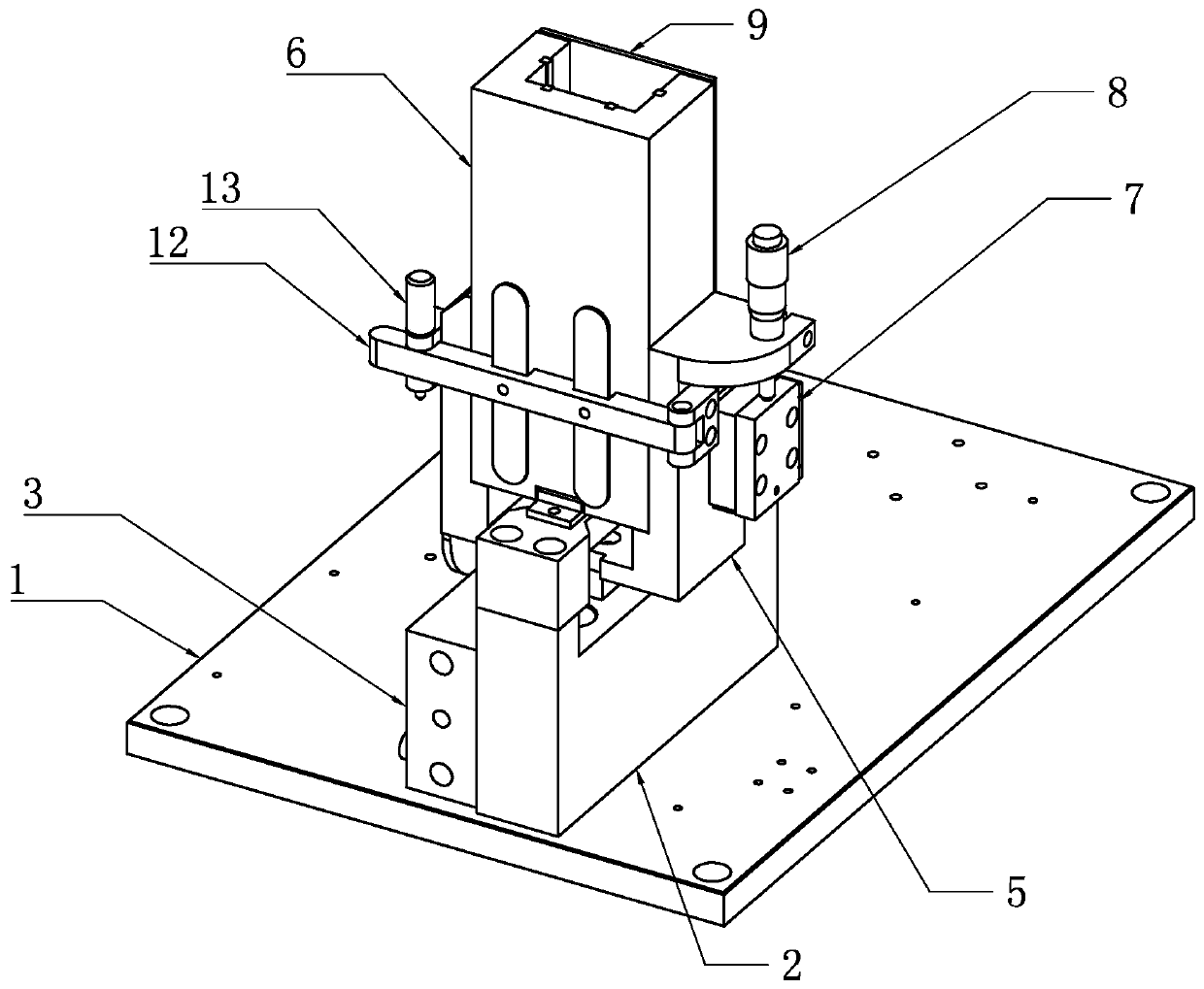
The invention relates to an automatic quartz plate loading system which comprises a feeding sliding table and a transfer device. The feeding sliding table comprises a magazine base and an air cylindermounted on a bottom plate, a first guide rail mounted on the magazine base, a second guide rail of a first material table mounted on the magazine base, a first slide block mounted on the first guiderail, a magazine mounted on the first slide block and a baffle plate matched with the magazine and the second guide rail to use jointly to form a quartz plate holding cavity. The transfer device comprises a servo motor mounted on the bottom plate, a back swing arm, a front swing arm and a transfer material table, wherein one end of the back swing arm is fixedly connected to an output shaft of theservo motor while the other end of the back swing arm is fixedly connected to a cylinder block of a swing air cylinder, one end of the front swing arm is fixedly connected to the output end of the swing arm air cylinder while the other end of the front swing arm is fixedly connected to a sucking disc, and the transfer material table is mounted on the bottom plate. The automatic quartz plate loading system is simple in structure and convenient to use, can transfer and load quartz plates automatically, and not only improves the work efficiency of an enterprise, but also meets the demand on automatic production of the enterprise.

Description

technical field [0001] The invention belongs to the technical field of crystal wafer feeding, in particular to an automatic crystal wafer feeding system. Background technique [0002] The crystal wafer needs to be loaded during the production and processing process. The crystal wafer needs to be placed on the predetermined loading position of the material table and then transported to the processing site of the next processing process. The traditional feeding method is to manually place a piece of The crystal wafer is sent to the quartz crystal fixture, and then placed on the material table through the fixture, the crystal wafer placed on the material table is absorbed by the suction head on the transfer device, and then transported to the next processing site by the transfer device Waiting for the next step of processing, the transfer device needs to continuously adjust the effective distance of the suction head according to the product specifications during the process of ...

Claims


Application Information

Patent Timeline
IPC IPC(8): B65G47/91
CPCB65G47/914
Inventor 许建峰邓见会朱中晓
Owner 北京石晶光电科技股份有限公司
Learn More