Supporting structure and display device

A support structure and flexible display technology, which is applied in the direction of identification devices, supporting machines, machine tables/supports, etc., can solve the problems of lower reliability and stability, bending resistance, and poor impact resistance, so as to improve reliability and Stability, enhanced impact resistance, and reduced processing deformation

Active Publication Date: 2020-02-14
BOE TECH GRP CO LTD
View PDF5 Cites 19 Cited by
  • Summary
  • Abstract
  • Description
  • Claims
  • Application Information

AI Technical Summary

Problems solved by technology

[0003] However, as the flexible display panel becomes lighter and thinner, the overall bending resistance and impact resistance are poor; the reliability and stability of the product are reduced

Method used


Image

  • Supporting structure and display device
  • Supporting structure and display device
  • Supporting structure and display device

Examples


Embodiment 1

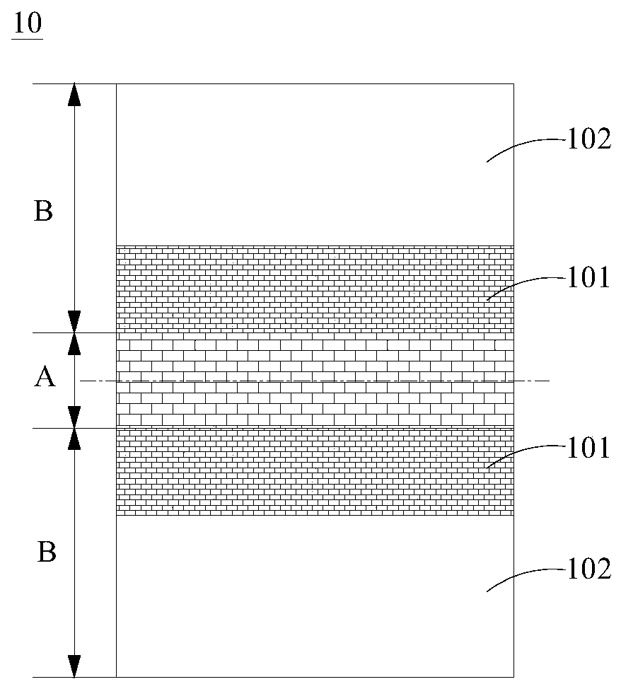
[0059] Such as figure 1 As shown, the first hollow holes in the bendable region A of the support structure 10 are arranged at equal intervals to ensure that the bendable region A can evenly disperse the stress during the bending process and avoid the occurrence of stress in the bendable region A. In the case of damage; in the same way, the second hollow holes of the buffer portion 101 in the fixed area B of the support structure 10 are arranged at equal intervals to ensure that the buffer portion 101 can disperse the stress more evenly during the bending process and avoid buffering. In the event of damage at the portion 101, the structural stability of the support structure 10 is ensured.

[0060] In this embodiment, the rigidity of the buffer portion 101 is slightly greater than the rigidity of the bendable region A, so that while eliminating or weakening the sudden change in rigidity at the junction of the fixed region B and the bendable region A, the support stability of th...

Embodiment 2

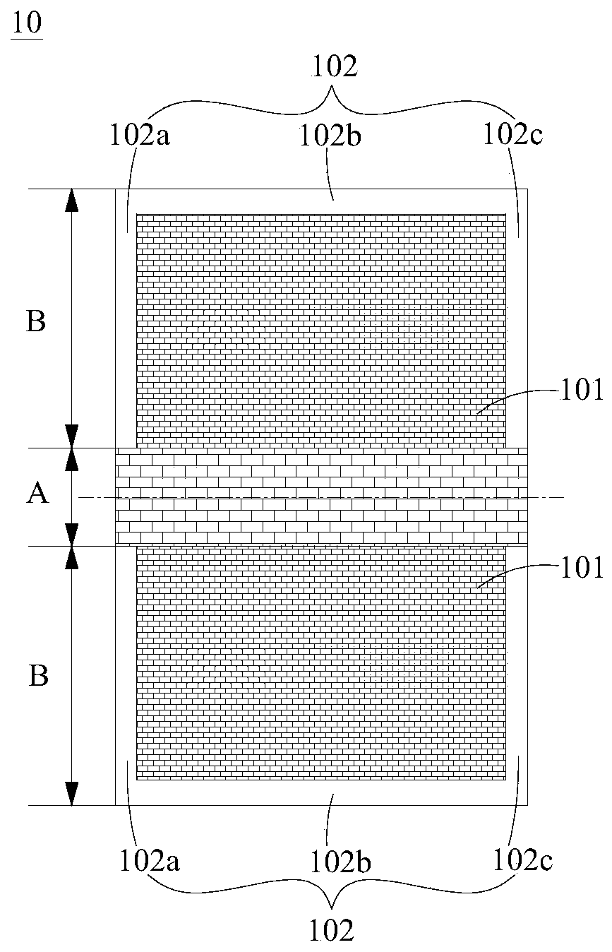
[0064] The main difference between the second embodiment and the first embodiment is: the shape of the rigid holding part 102 in the fixed area B, the positional relationship between the rigid holding part 102 and the buffer part 101, the area ratio, etc.; while other design methods are the same as those of the first embodiment The same, for example: the pattern of the buffer portion 101 , the pattern of the bendable region A, the rigid relationship between the buffer portion 101 and the bendable region A, and so on. However, it should be understood that other design methods may not be the same as in the first embodiment, as long as the general design requirements of the present application can be met.

[0065] Only the differences between this embodiment and the first embodiment will be described in detail below.

[0066] Such as figure 2 As shown, the rigid holding portion 102 in the fixing area B is in the shape of a U-shaped strip, and the U-shaped rigid holding portion ...

Embodiment 3

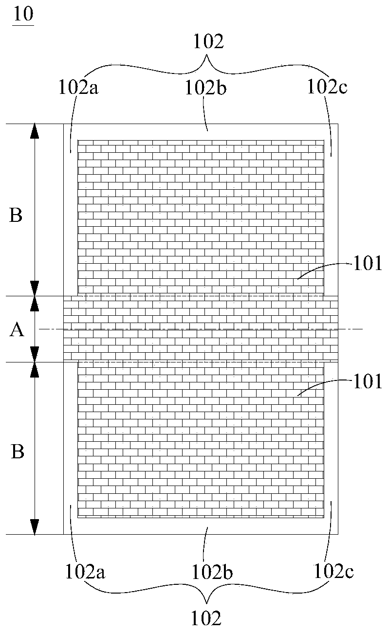
[0069] The main difference between the third embodiment and the second embodiment is: the rigid relationship between the buffer portion 101 in the fixed area B and the bendable area A, etc.; and other design methods are the same as the second embodiment, for example: the bending area A The pattern, the shape of the rigid holding portion 102 in the fixed area B, the positional relationship and area ratio between the rigid holding portion 102 and the buffer portion 101 , etc. However, it should be understood that other design methods may not be the same as in Embodiment 2, as long as the general design requirements of the present application can be met.

[0070] Only the differences between this embodiment and the second embodiment will be described in detail below.

[0071] Such as image 3 As shown, the rigidity of the buffer portion 101 is equal to the rigidity of the bendable region A, so as to basically eliminate the sudden change in rigidity at the junction of the fixed r...


PUM


Abstract

The invention relates to the technical field of display, and particularly relates to a supporting structure and a display device. The supporting structure is arranged on one side of a flexible displaypanel and comprises a bendable area and fixing areas, wherein the bending axis corresponding to the bendable area extends in the first direction, and a plurality of first hollowed-out holes are formed in the bendable area; the fixing areas are positioned on the two opposite sides of the bendable area in the second direction, and the second direction intersects with the first direction; each fixing area is provided with a rigidity keeping part and a buffering part provided with a plurality of second hollowed-out holes; the buffering parts are connected with the bendable area, and the rigidityof the buffering parts is larger than or equal to that of the bendable area; at least part of the rigidity keeping parts are arranged on the sides, away from the bendable area, of the buffering parts,and the rigidity of the rigidity keeping parts is larger than that of the buffering parts. By means of the design, the structural stability of the supporting structure can be guaranteed, and the impact resistance and bending resistance of the flexible display panel are enhanced.

Description

technical field [0001] The present application relates to the field of display technology, in particular, to a support structure and a display device. Background technique [0002] With the development of display technology, flexible display panels such as foldable, stretchable and rollable are gradually entering the sight of consumers. In order to facilitate bending or recovery of the flexible display panel, it is necessary to make the flexible display panel thinner and lighter. [0003] However, as the flexible display panel becomes lighter and thinner, the overall bending resistance and impact resistance are poor; the reliability and stability of the product are reduced. [0004] It should be noted that the information disclosed in the above background technology section is only used to enhance the understanding of the background of the application, and therefore may include information that does not constitute prior art known to those of ordinary skill in the art. Con...

Claims


Application Information

Patent Timeline
Patent Type & Authority Applications(China)
IPC IPC(8): F16M11/40G09F9/00
CPCF16M11/40G09F9/00G09F9/301G06F1/1652G06F1/1656G06F1/1601
Inventor 曹方旭王浩然董栗明周永红
Owner BOE TECH GRP CO LTD
Why Eureka
Try Eureka