High-power tile type phased-array antenna

A phased array antenna and tile-type technology, which is applied in the field of communication, can solve the problems of chip heating, inability to apply high-power applications, poor chip heat dissipation, etc., to increase heat dissipation, increase heat dissipation effect, and meet heat dissipation requirements.

Active Publication Date: 2020-02-14
成都华芯天微科技有限公司
View PDF8 Cites 8 Cited by
  • Summary
  • Abstract
  • Description
  • Claims
  • Application Information

AI Technical Summary

Problems solved by technology

[0005] In order to solve the problem that the existing tile-type phased array antenna has a poor internal chip heat dissipation effect, which makes it unsuitable for high-power applications, the purpose of the present invention is to provide a real-time solution to the problem of chip heating in the antenna, so as to truly realize Tile Phased Array Antenna for High Power Transmission

Method used


Image

  • High-power tile type phased-array antenna
  • High-power tile type phased-array antenna
  • High-power tile type phased-array antenna

Examples


Embodiment 1

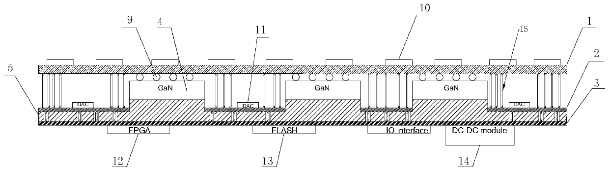
[0046] Such as Figure 1-8 As shown, the high-power tile-type phased array antenna provided in this embodiment includes a first printed circuit board layer 1 , a second printed circuit board layer 2 and a third printed circuit board layer 3 arranged in sequence.

[0047] The first printed circuit board layer 1 is used for transmitting radio frequency signals and implementing a 64-unit power division network.

[0048] The second printed circuit board layer 2 is electrically connected to the first printed circuit board layer 1 for phase shifting and attenuation of control signals.

[0049] The third printed circuit board layer 3 is electrically connected to the second printed circuit board layer 2 for power supply and signal input control.

[0050] Several chips 4 for signal output are arranged on the first printed circuit board layer 1 .

[0051]A heat dissipation cold plate 5 is also provided between the second printed circuit board layer 2 and the third printed circuit boar...

Embodiment 2

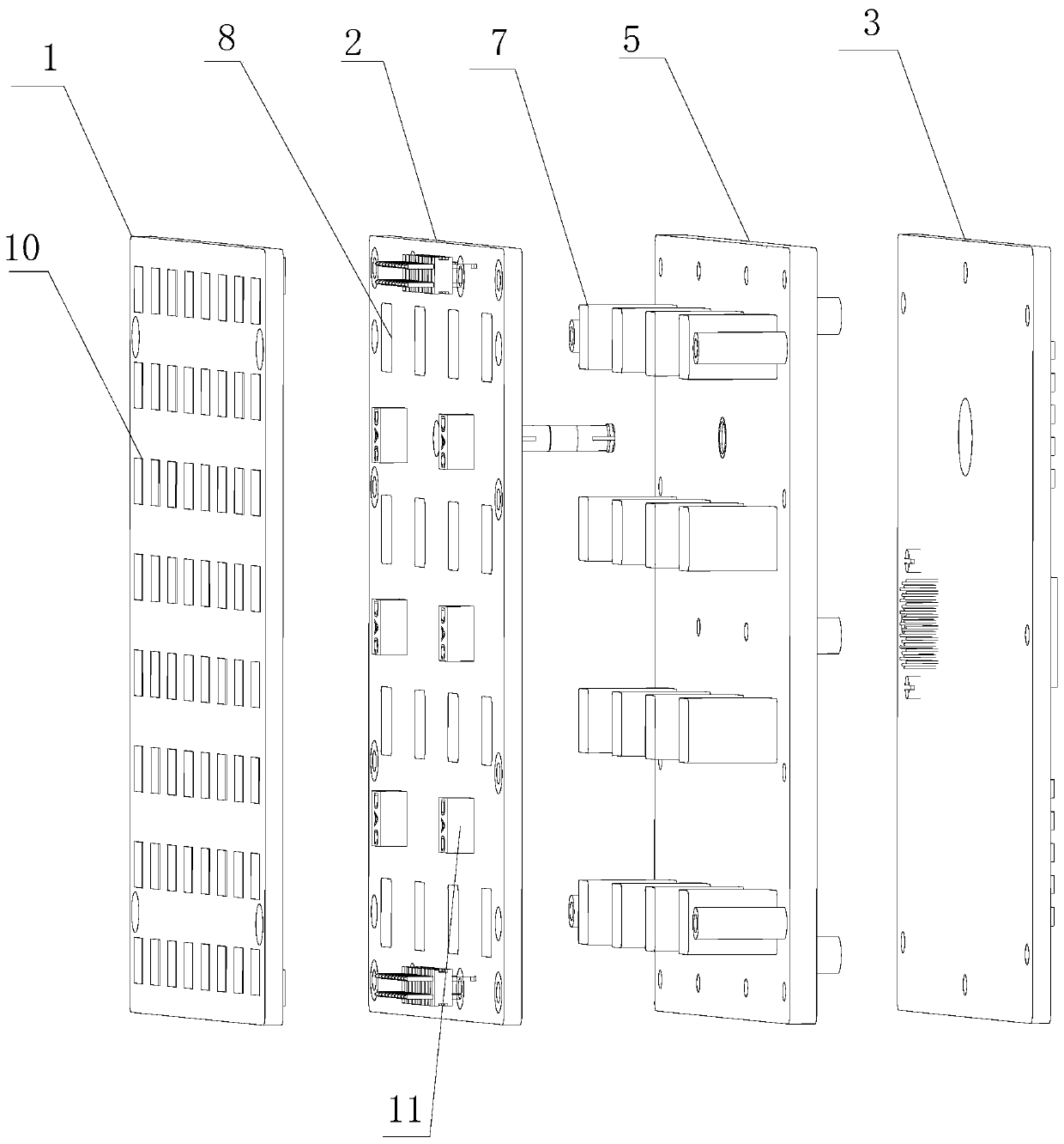
[0063] Such as Figure 1-8 As shown, this embodiment is a specific implementation of the high-power tile-type phased array antenna described in Embodiment 1.

[0064] The following is a detailed description of the structure of the phased array antenna:

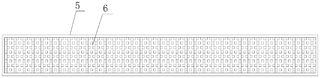
[0065] Such as figure 1 , figure 2 and image 3 As shown, the specific structure of the heat dissipation cold plate is described below:

[0066] Optimally, the heat dissipation cold plate 5 is a hollow plate, wherein a capillary heat dissipation channel 6 is provided in the inner cavity of the heat dissipation cold plate 5 , and a heat dissipation liquid is stored in the capillary heat dissipation channel 6 .

[0067] The surface of the heat dissipation cold plate 5 facing the second printed circuit board layer 2 is provided with a number of heat dissipation bosses 7 equal in number to the chips 4 .

[0068] Each heat dissipation boss 7 is used as a heat absorbing end of the heat dissipation cold plate 5 , and contacts t...


PUM


Abstract

The invention discloses a high-power tile type phased-array antenna, comprising a first printed circuit board layer, a second printed circuit board layer and a third printed circuit board layer whichare arranged in sequence. The first printed circuit board layer is used for transmitting radio frequency signals and realizing a 64-unit power division network. The second printed circuit board layeris electrically connected with the first printed circuit board layer and is used for controlling phase shift and attenuation of signals. The third printed circuit board layer is electrically connectedwith the second printed circuit board layer and is used for power supply and signal input control. A plurality of chips for signal output are arranged on the first printed circuit board layer. A heatdissipation cold plate is arranged between the second printed circuit board layer and the third printed circuit board layer, and the heat absorption end of the heat dissipation cold plate is in contact with the chips. According to the invention, the problem of chip heating in the antenna can be solved in real time, and high-power transmission of signals can be truly realized.

Description

technical field [0001] The invention relates to the technical field of communications, in particular to a high-power tile-type phased array antenna. Background technique [0002] Traditional radar phased array antennas mainly use brick-type T / R components or tile-type T / R components. The traditional brick-type integration method mainly refers to: T / R components adopt vertical layout and horizontal assembly integration form; The tile-type integration method mainly refers to: T / R components adopt the integration form of horizontal layout, vertical assembly, and vertical interconnection. [0003] The traditional brick-type antenna has a large vertical size, heavy weight, low integration, and high requirements on the scale of the feed network, while the tile-type antenna has a series of high-density integration, low profile, light weight, and low mass production cost. advantages, so that a large number of applications can be obtained. [0004] However, the current tile-type ph...

Claims


Application Information

Patent Timeline
Patent Type & Authority Applications(China)
IPC IPC(8): H01Q1/00H01Q21/00H01Q23/00
CPCH01Q1/02H01Q21/00H01Q21/0006H01Q23/00
Inventor 汪渊
Owner 成都华芯天微科技有限公司
Why Eureka
Try Eureka