A high-power rolling slip ring device
What is Al technical title?
Al technical title is built by PatSnap Al team. It summarizes the technical point description of the patent document.
A bus ring, high-power technology, applied in current collectors, electrical components, rotary current collectors, etc., can solve the problems of shortening the service life of the bus ring device, reducing the electrical performance of the bus ring device, etc., and achieves low cycle cost and structure. Simple, low-wear effect
Active Publication Date: 2017-04-05
SHANGHAI SPACEFLIGHT ELECTRONICS & COMM EQUIP RES INST
View PDF4 Cites 0 Cited by
Summary
Abstract
Description
Claims
Application Information
AI Technical Summary
This helps you quickly interpret patents by identifying the three key elements:
Problems solved by technology
Method used
Benefits of technology
Problems solved by technology
However, when this kind of slip ring works, sliding friction is formed between the contact surfaces. As the working time prolongs, wear debris will be generated, and the wear debris will continue to accumulate on the contact surface, which will reduce the electrical performance of the slip ring device and shorten the life of the slip ring device. service life
Method used
Image
Click on the blue label to locate the original text in one second.
Reading with bidirectional positioning of images and text.
Examples
Embodiment Construction
[0027] The present invention will be described in detail below in conjunction with the accompanying drawings. In order to enable those skilled in the art to clearly and completely understand the contents of the present invention and implement the technical solutions of the present invention, a large number of details are disclosed in the embodiments. However, obviously, without these details, those skilled in the art can also implement the technical solution of the present invention, achieve the purpose of the present invention, and achieve the effect of the present invention. These details are the optimal implementation mode selected by the inventor through a large number of experiments, and are not used to limit the protection scope of the present invention. The scope of protection of the present invention is based on the content of the claims, and technical solutions obtained by those skilled in the art based on the content disclosed in this application document without cre...
PUM
Abstract
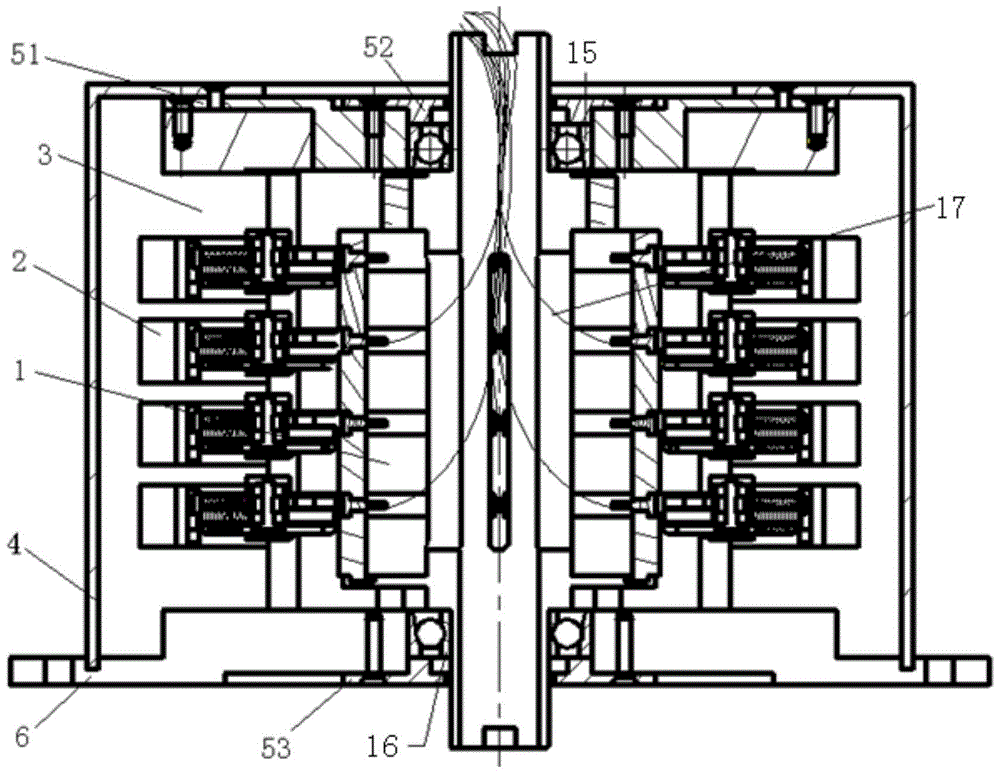
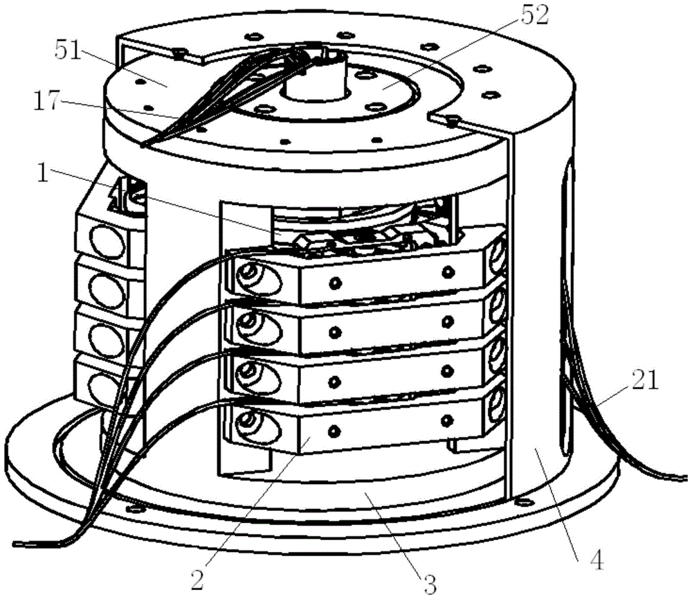
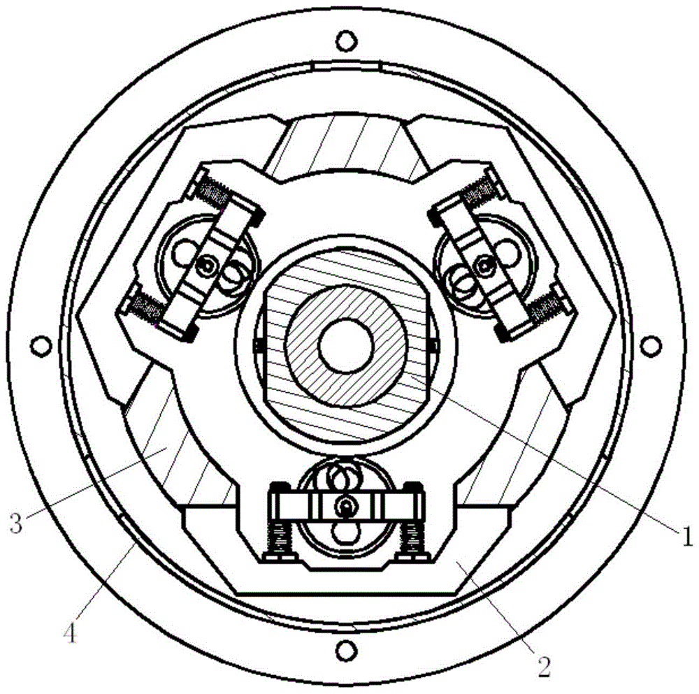
The invention provides a high-power rolling collector ring device. The high-power rolling collector ring device comprises rolling circle rotor assemblies, a fixed supporting seat and multiple rolling block assemblies. Each rolling circle rotor assembly comprises a main shaft, multiple conductive rings, multiple separating rings and a fastening component, wherein the conductive rings and the separating rings are arranged on the main shaft in a sleeved mode at intervals, and the main shaft is connected with the fixed supporting seat through first bearings. Each rolling block assembly comprises a stand, two guiding rods, two adjusting nuts, two compressed springs, a base plate, two first checking rings, a rolling block and multiple flexible rings, wherein the stand is connected with the fixed supporting seat, the guiding rods are connected with the stand, the adjusting nuts, the compressed springs, the base plate and the first checking rings are sequentially arranged on the guiding rods in a sleeved mode, the adjusting nuts are connected with the guiding rods in a threaded mode, a rotary shaft of the rolling block is connected with the base plate through second bearings, the flexible rings are arranged on the inner side of the rolling block in an embedded mode, and the outer side of the rolling block can be in contact with the conductive rings. Due to the rolling contact between the conductive rings and the rolling blocks and the rolling contact between the rolling blocks and the flexible rings, transmitting of an electric signal and power is carried out, the abrasion is low, abrasive fragments do not exist, the service life is long, and the electric performance is good.
Description
technical field [0001] The invention relates to a slip ring device, in particular to a high-power rolling slip ring device. Background technique [0002] Slip rings have a wide range of demands in the fields of aerospace, aviation, navigation and various precision instruments. The bus ring is used to realize the transmission of electric power or electric signal between two relatively rotating parts, so as to avoid twisting and breaking the wire during relative rotation. [0003] At present, the commonly used slip ring device mainly realizes this transmission function through the frictional contact between the fixed wire brush (or carbon brush) and the rotating ring. However, when this kind of slip ring works, sliding friction is formed between the contact surfaces. As the working time prolongs, wear debris will be generated, and the wear debris will continue to accumulate on the contact surface, which will reduce the electrical performance of the slip ring device and shorte...
Claims
Application Information
Patent Timeline
Application Date:The date an application was filed.
Publication Date:The date a patent or application was officially published.
First Publication Date:The earliest publication date of a patent with the same application number.
Issue Date:Publication date of the patent grant document.
PCT Entry Date:The Entry date of PCT National Phase.
Estimated Expiry Date:The statutory expiry date of a patent right according to the Patent Law, and it is the longest term of protection that the patent right can achieve without the termination of the patent right due to other reasons(Term extension factor has been taken into account ).
Invalid Date:Actual expiry date is based on effective date or publication date of legal transaction data of invalid patent.
Patent Type & Authority Patents(China)
IPC IPC(8): H01R39/64H01R39/28
Inventor 徐雄李国民陈同辉李慧师雪丽翁艺航
Owner SHANGHAI SPACEFLIGHT ELECTRONICS & COMM EQUIP RES INST