Eureka AIR delivers breakthrough ideas for toughest innovation challenges, trusted by R&D personnel around the world.

Automatic machining equipment for intelligent socket

A technology for processing equipment and smart sockets, applied in the field of automated processing equipment for smart sockets, can solve problems such as assembly difficulties, affecting socket processing efficiency, and damaging snap-on structures.

Pending Publication Date: 2020-02-14
湖南泰达讯科技有限公司
View PDF0 Cites 0 Cited by
  • Summary
  • Abstract
  • Description
  • Claims
  • Application Information

AI Technical Summary

Problems solved by technology

[0003] Existing smart sockets are more and more widely used. However, the existing smart sockets often have the following defects during use. First, the existing smart sockets often have a snap-fit ​​assembly structure, but then use bolts Reinforcement, however, deflection often occurs during buckle assembly, making assembly more difficult, and it is also easy to cause damage to the snap-fit ​​structure during assembly; secondly, the existing smart sockets often use manual assembly during assembly, often Affect the processing efficiency of the socket

Method used


Image

  • Automatic machining equipment for intelligent socket
  • Automatic machining equipment for intelligent socket
  • Automatic machining equipment for intelligent socket

Examples


Embodiment 1

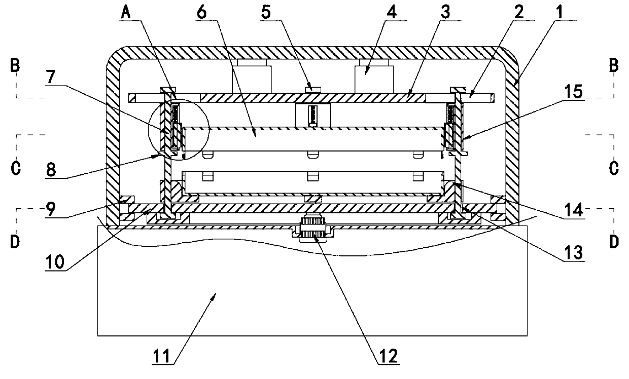
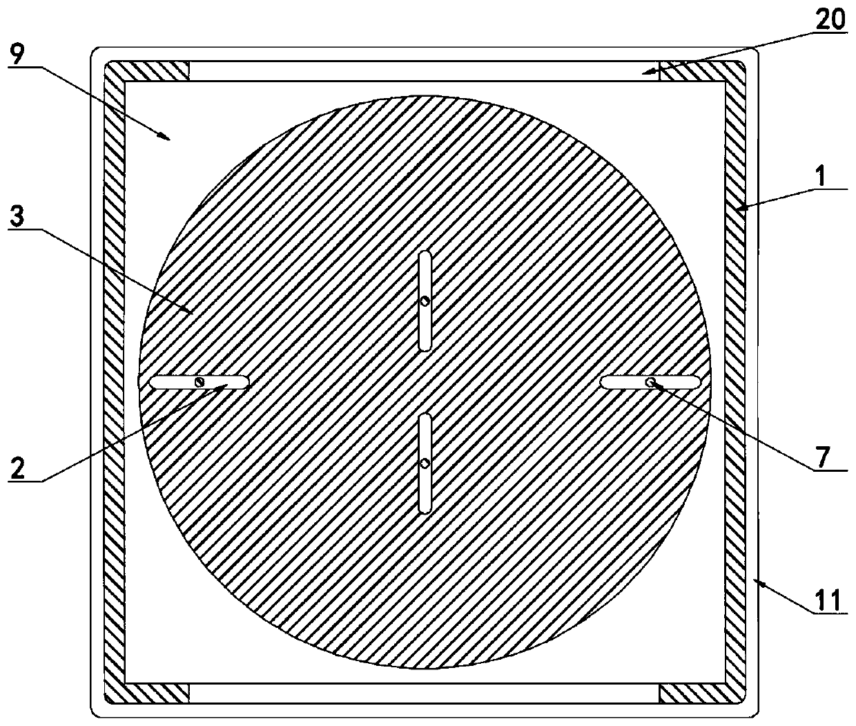
[0027] Embodiment one, with reference to Figure 1-5 , an automatic processing equipment for intelligent sockets, including a base 11 and a bracket 1 set on the base 11, an electric telescopic rod 4 is fixedly connected to the lower end surface of the top of the bracket 1, two socket housings 6 are arranged inside the bracket 1, and the base 11 A driving motor 12 is fixedly connected to the center of the end face, a turning slot 9 is provided on the inner side of the bottom of the support 1, and a second horizontal plate 10 is connected to the inside of the turning slot 9, and a first horizontal plate 3 is fixedly connected to the lower end surface of the electric telescopic rod 4, and The first horizontal plate 3 is provided with four first chute 2, and the inside of the four first chute 2 is slidably connected with a slide bar 7, and the second horizontal plate 10 is provided with a second chute 13, and the second chute 2 The groove 13 is slidingly connected with the slide b...

Embodiment 2

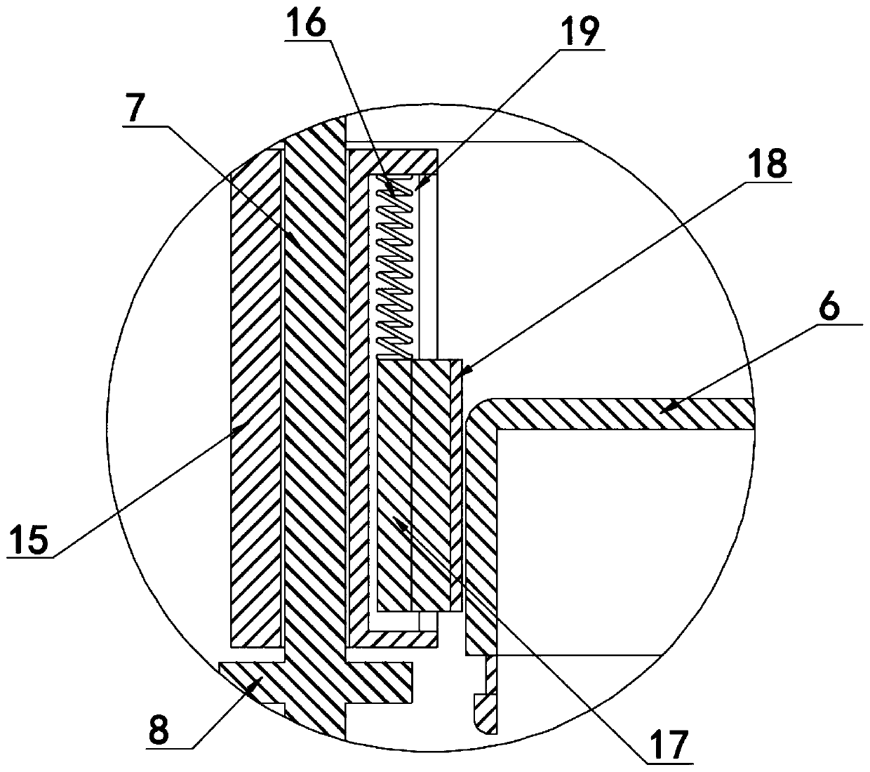
[0028] Embodiment two, refer to figure 1 and 2 , the top of the slide bar 7 is fixedly connected to the limit block 5, and the lower end surface of the limit block 5 is attached to the upper end surface of the first horizontal plate 3, and the side of the slide bar 7 is fixedly connected with a snap ring 8, and the snap ring 8 is connected to the sliding sleeve 15, the lower end surface is fitted and extruded so that the stopper 5 can limit the vertical direction of the slide bar 7, and at the same time, the snap ring 8 can limit the vertical direction of the sliding sleeve 15, so that the sliding sleeve 15 can hold the top The socket housing 6 is accurately aligned and fixed.

Embodiment 3

[0029] Embodiment three, refer to Figure 1-5 , the first chute 2, the slide bar 7 and the second chute 13 are all provided with four, and the four first chute 2 are all in a linear structure, and the adjacent two of the four first chute 2 The included angles are all 90°, and the four second chute 13 are in a semi-elliptical structure. One side of each sliding sleeve 15 close to the socket housing 6 is provided with a limit chute 19, the limit chute 19 and the limit slide 17 limit slide, and the limit slide 17 upper surface passes through the compression spring 16 and the limit slide. The bottom surface of the top of the groove 19 is elastically connected, so that the sliding bar 7 reciprocates close and far away under the joint action of the second sliding groove 13 and the first sliding groove 2 .


PUM


Abstract

The invention discloses automatic machining equipment for an intelligent socket. The equipment comprises a base and a bracket arranged on the base, wherein a lower end face of the top of the bracket is fixedly connected with an electric telescopic rod, two socket shells are arranged in the bracket, a driving motor is fixedly connected with the center of an upper end face of the base, a rotating groove is formed on an inner side of the bottom of the bracket, a second horizontal plate is rotatably connected into the rotating groove, a first horizontal plate is fixedly connected with a lower endface of the electric telescopic rod, and the two socket shells are attached to a buffer pad and the clamping block respectively in an extruding mode. The equipment is advantaged in that a four-way limiting structure is adopted, four sliding rods drive the clamping blocks at the same time to clamp the socket shells, an up-down overlapping alignment structure is adopted, the two socket shells are stably limited and aligned, and a spring extrusion structure is adopted, so a compression spring pushes the two socket shells to be clamped at the same time.

Description

technical field [0001] The invention belongs to the technical field of socket processing equipment, in particular to automatic processing equipment for intelligent sockets. Background technique [0002] In layman's terms, smart sockets are a kind of sockets that save electricity. The concept of energy-saving sockets has been generated a long time ago, and it has been widely developed so far, but the technology still needs to be improved. Electricity can also protect electrical appliances. It can be connected to handheld devices through Wifi, Bluetooth, etc. The main functions are remote switch and voice control. [0003] Existing smart sockets are more and more widely used. However, the existing smart sockets often have the following defects during use. First, the existing smart sockets often have a snap-fit ​​assembly structure, but then use bolts Reinforcement, however, deflection often occurs during buckle assembly, making assembly more difficult, and it is also easy to ...

Claims


Application Information

Patent Timeline
Patent Type & Authority Applications(China)
IPC IPC(8): H01R43/20
CPCH01R43/20
Inventor 陈良玖
Owner 湖南泰达讯科技有限公司
Why Eureka
Eureka Blog
Learn More