
DC power supply unit control detection system and method

A DC power supply and unit control technology, applied in control/regulation systems, electrical components, DC power input conversion to DC power output, etc., can solve problems such as busbar fluctuations, unfavorable power grids, and inability to quickly track, save costs, avoid Effects of loss and inconvenience

Inactive Publication Date: 2020-02-14
SICHUAN INJET ELECTRIC CO LTD
View PDF17 Cites 4 Cited by
  • Summary
  • Abstract
  • Description
  • Claims
  • Application Information

AI Technical Summary

Problems solved by technology

In order to quickly track the changes of the load and the power grid, the PID output will fluctuate greatly, which will lead to bus fluctuations
Especially when the power grid is weak, the fluctuation of the bus will cause the input current to change, which will lead to the imbalance of the three-phase input current, which is not good for the power grid.
There is also a way to filter the feedback, and design a low-pass filter to filter out the 300Hz AC component, but this will cause the feedback to lag, and it will not be able to track quickly when the load or power grid changes suddenly

Method used


Image

  • DC power supply unit control detection system and method
  • DC power supply unit control detection system and method
  • DC power supply unit control detection system and method

Examples


Embodiment 1

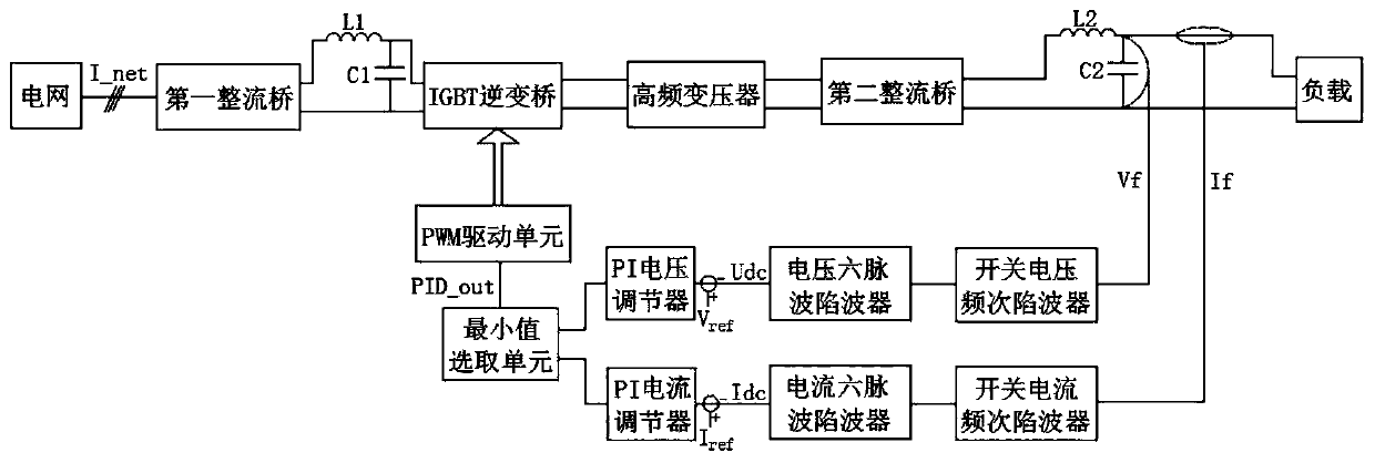
[0033] The present invention is realized through the following technical solutions, as figure 1 As shown, a DC power supply unit control and detection system is connected to the DC power supply unit, the input end of the DC power supply unit is connected to the power grid, and the bus output end of the DC power supply unit is connected to a load. The DC power supply unit includes sequentially connected The first rectifier bridge, the IGBT inverter bridge, the high-frequency transformer, and the second rectifier bridge, the input end of the first rectifier bridge is connected to the grid, the output end of the first rectifier bridge is connected to the input end of the IGBT inverter bridge, and the IGBT The output end of the inverter bridge is connected to the input end of the high-frequency transformer, the output end of the high-frequency transformer is connected to the input end of the second rectifier bridge, and the output end of the second rectifier bridge is respectively ...


PUM


Abstract

The invention relates to a DC power supply unit control detection system and method. The DC power supply unit control detection system is connected with a DC power supply unit. The input end of the DCpower supply unit is connected with a power grid, and the output end is connected with a load. The system comprises a switching frequency trap filter, a six-pulse trap filter, a PI regulator, a minimum value selection unit and a PWM driving unit which are connected in sequence. The DC power supply unit comprises an IGBT inverter bridge. The input end of the switching frequency trap filter is connected with the bus output end of the DC power supply unit. The output end of the PWM driving unit is connected with the IGBT inverter bridge. High-frequency switching ripples and six-pulse ripples arefiltered through the trap filters, and quick response of feedback signals at the bus output end of the DC power supply unit cannot be affected. When the power grid suddenly changes or the load suddenly changes, the PWM duty ratio of the IGBT inverter bridge can be rapidly adjusted and controlled, so that the output of the DC power supply unit is rapidly reduced, shutdown faults such as over-current and overload cannot be caused, and loss and inconvenience brought to the load of a user side are avoided.

Description

technical field [0001] The invention relates to the technical field of DC power supply control, in particular to a control and detection system and method for a DC power supply unit. Background technique [0002] Many industrial sites need to heat the load, and when it comes to heating, it is necessary to control the output power of the power supply, and then control the temperature of the load. The traditional thyristor power supply controls the thyristor switch, then steps down the voltage through a power frequency transformer, and outputs a large current to heat the load. This type of power transformer is bulky and is gradually replaced by a high frequency IGBT power supply. For heating loads, the temperature inertia is relatively large, and the load temperature can be stabilized only after the average power is stabilized for a long time, so there is basically no requirement for the output ripple of the power supply. Based on this, in order to save costs, the rectified a...

Claims


Application Information

Patent Timeline
Patent Type & Authority Applications(China)
IPC IPC(8): H02M7/217H02M3/335
CPCH02M3/335H02M7/217
Inventor 刘洋康智斌任青云
Owner SICHUAN INJET ELECTRIC CO LTD
Learn More