Motor drive control device, motor, and blowing device

A drive control and motor technology, applied in the fields of motors, air supply devices, and motor drive control devices, can solve the problems of time-consuming, repeated failures, etc., and achieve the effect of improving the success rate of starting

Pending Publication Date: 2020-02-14
NIPPON DENSAN CORP
View PDF1 Cites 0 Cited by
  • Summary
  • Abstract
  • Description
  • Claims
  • Application Information

AI Technical Summary

Problems solved by technology

When the transition to sensorless control fails, in order to restart the brushless DC motor, initial processing such as short-time braking is performed to stop the rotor, and then forced commutation is performed, so starting takes time
In addition, if the forced commutation is repeated only after the initial processing, the transfer to the sensorless control may repeatedly fail.

Method used


Image

  • Motor drive control device, motor, and blowing device
  • Motor drive control device, motor, and blowing device
  • Motor drive control device, motor, and blowing device

Examples


Embodiment Construction

[0016] Hereinafter, exemplary embodiments of the present invention will be described with reference to the drawings.

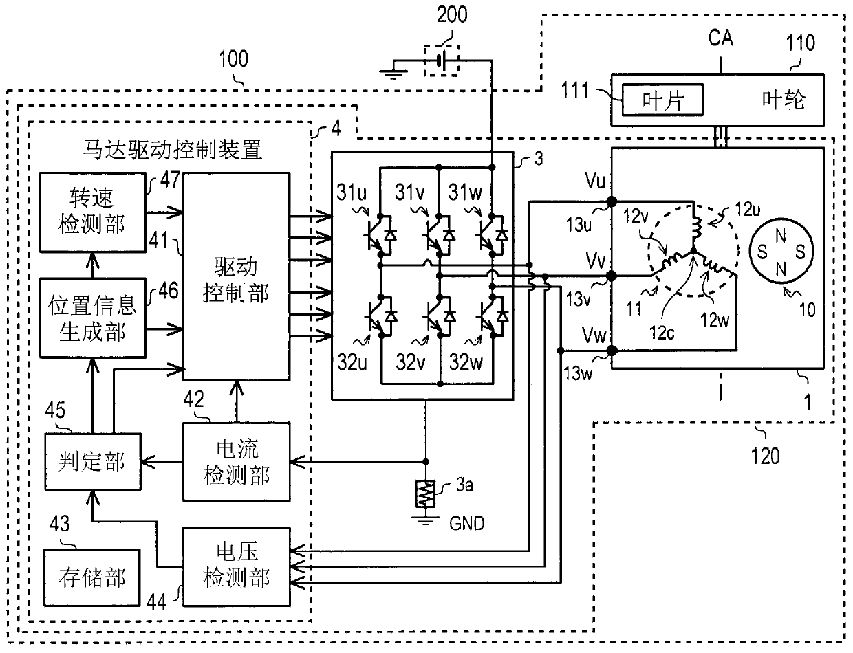
[0017] In addition, in this specification, in the air blower 100, the direction parallel to the central axis CA of rotation of the motor part 1 and the blade 111 is called "axial direction."

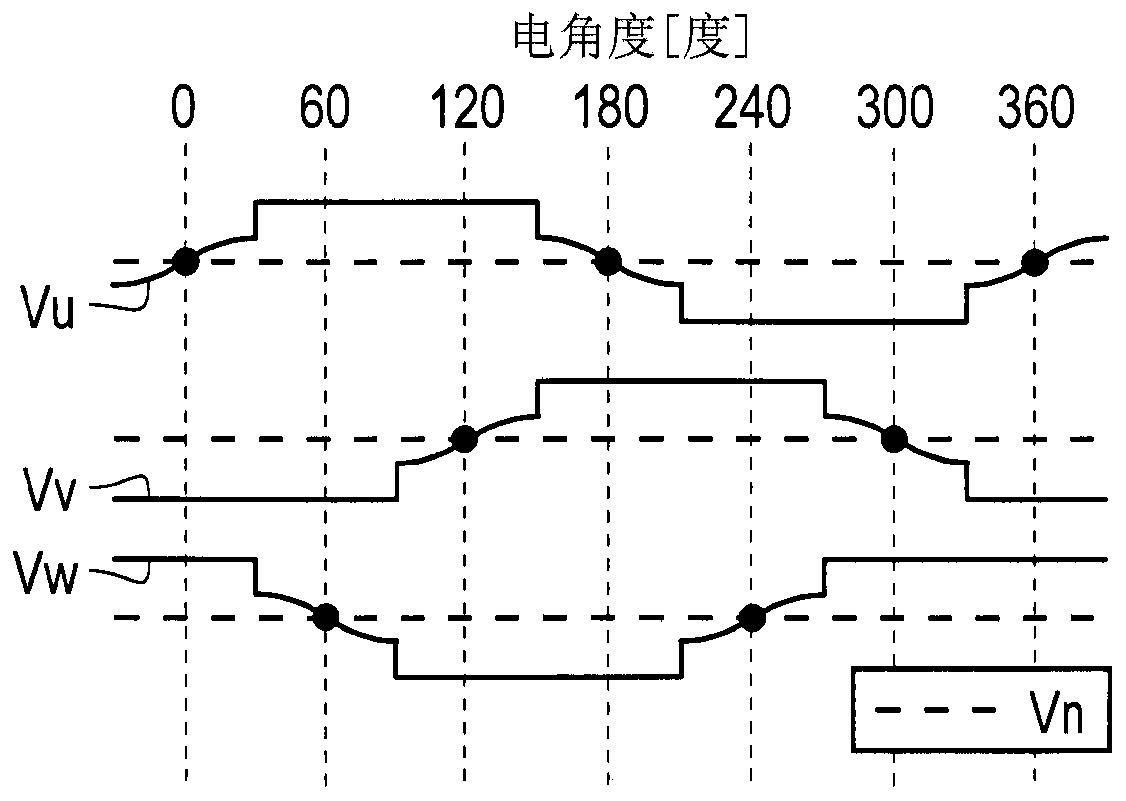
[0018] The U-phase winding 12u, the V-phase winding 12v, and the W-phase winding 12w of the stator 11 of the motor unit 1 may be individually or collectively referred to as a phase winding 12 . The phase that energizes the phase winding 12 in the three-phase AC voltage is called an energized phase, and the phase that does not energize the phase winding 12 is called a non-energized phase. In addition, the combination of two energized phase windings 12 is called an energization pattern. In addition, the U-phase voltage, the V-phase voltage, and the W-phase voltage of the three-phase AC voltage are sometimes called phase voltages individually or collectively.

[0019]

...


PUM


Abstract

The invention provides a motor drive control device, a motor and a blowing device. The motor drive control device comprises a drive control part, which controls the drive of a motor to which a three phase AC voltage is applied, and switches the electrifying modes of the phase windings of the motor; a voltage detection part, which detects the voltage of the phase windings; and a position information generation part, which generates the position information of the rotation direction of the rotor of the motor based on the detection results of the voltage detection part. The drive control part candetect the rotation direction position of the rotor as any rotation direction position from a first rotation direction position to a sixth rotation direction position which are divided according to an electrical angle of 60 degrees based on specified rotation direction position information after energization. A lower synchronous operation for switching the energization mode in accordance with therotational direction position information is started. On the other hand, when the drive control unit cannot detect the position in the arbitrary rotation direction, energization in the energization mode is added.

Description

technical field [0001] The invention relates to a motor drive control device, a motor and an air blower. Background technique [0002] Conventionally, an air blower equipped with a brushless DC motor of a sensorless control method is known. In the brushless DC motor of the sensorless control system, the position in the rotational direction of the rotor is detected based on the induced voltage generated by the rotor. However, when the motor is started, the rotor is stopped or rotated at a low speed, so the position in the rotational direction of the rotor cannot be detected. Therefore, for example, in Japanese Patent Application Laid-Open No. 2010-045941, the rotor is raised to a certain rotational speed by forced commutation, then the forced commutation is stopped to rotate the rotor by inertia, and the position in the rotational direction of the rotor is detected in this state. Move to sensorless control. [0003] Patent Document 1: Japanese Patent Laid-Open No. 2010-045...

Claims


Application Information

Patent Timeline
Patent Type & Authority Applications(China)
IPC IPC(8): H02P6/18
CPCH02P6/18H02P2203/09
Inventor 窪田雅弘松崎和哉
Owner NIPPON DENSAN CORP
Why Eureka
Try Eureka