Measuring probe for beam scanning

A beam and probe technology, applied in the field of scanning beam or laser beam devices, can solve problems such as inaccurate scanning results and changes in beam characteristics

Active Publication Date: 2020-02-14
普莱姆斯激光测量技术有限公司
View PDF11 Cites 0 Cited by
  • Summary
  • Abstract
  • Description
  • Claims
  • Application Information

AI Technical Summary

Problems solved by technology

However, the beam to be measured may have to travel a longer path through the scanning volume before the beam is scanned by the probe area
This in turn can lead to undesired changes in beam characteristics due to refraction and thermo-optical effects, leading to inaccurate scan results
[0014] Therefore, the devices and methods known from the prior art have significant disadvantages in terms of usability, achievable spatial resolution and / or in terms of measurement accuracy or signal-to-interference light distance at very high laser powers or power densities

Method used


Image

  • Measuring probe for beam scanning
  • Measuring probe for beam scanning
  • Measuring probe for beam scanning

Examples


Embodiment Construction

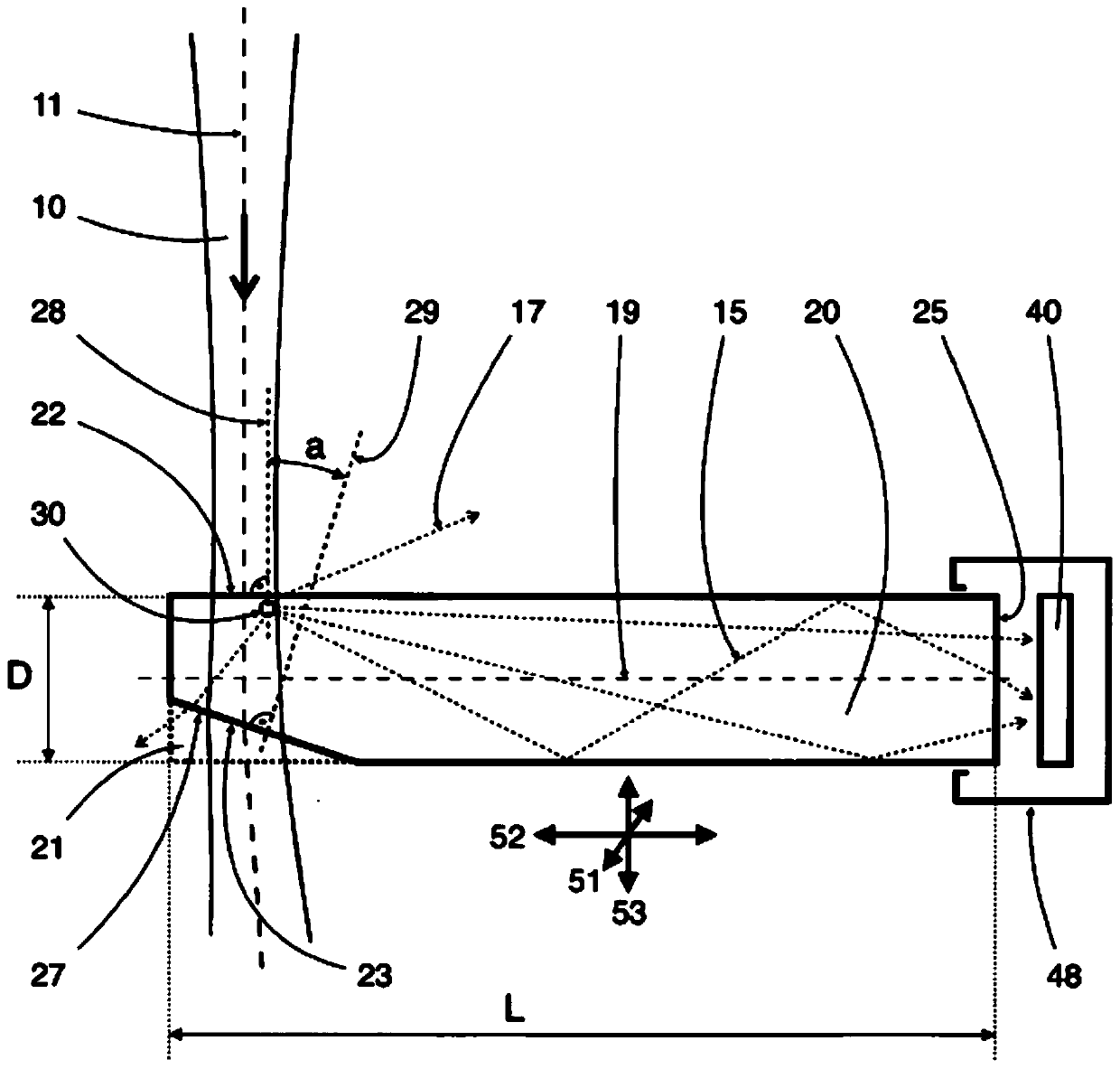
[0099] The invention proposes a solution to the problem that the devices for beam analysis known from the prior art are inaccurate or can be destroyed when applying beams or laser beams with very high power, and Consequences may occur due to scattered light, for example due to multiple reflections with erroneous signals. Instead, a device for scanning a light beam is provided which is suitable for determining geometric parameters of high-power or high-power-density laser beams, is insensitive to scattered light and enables measurements with a high signal-to-noise ratio.

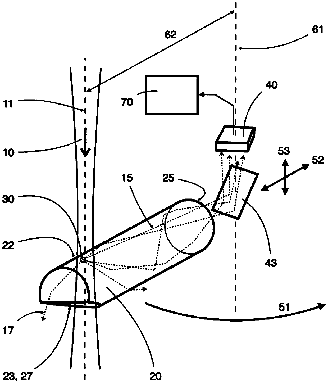
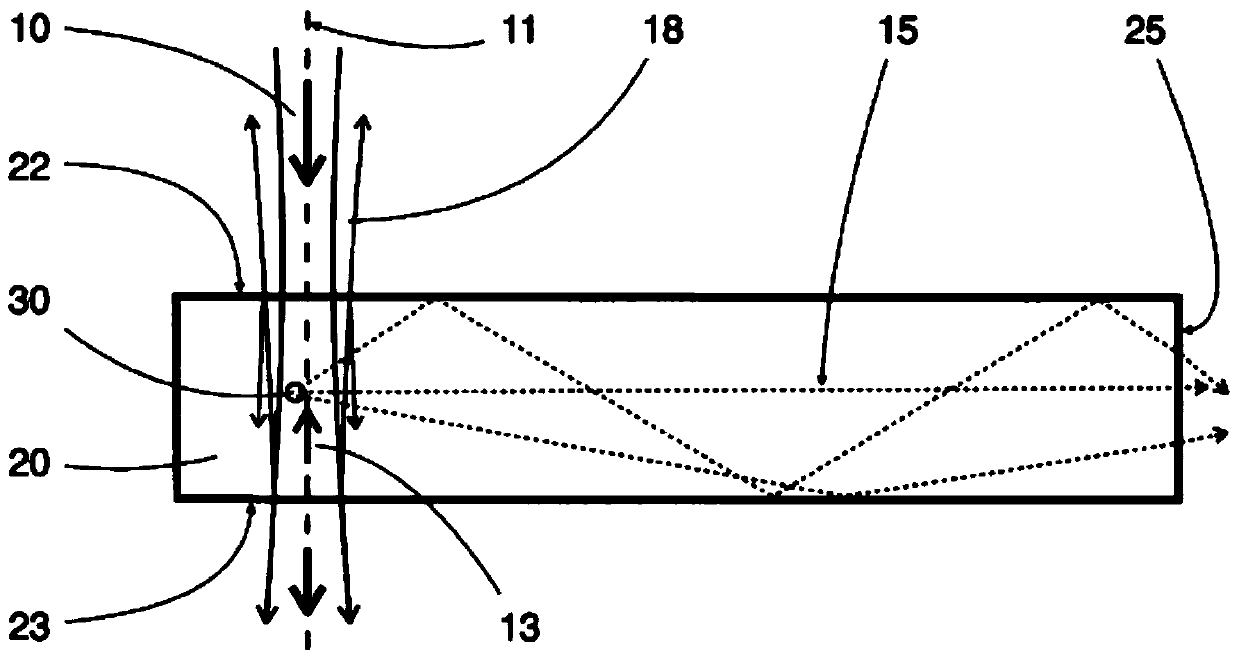
[0100] In order to solve this problem, a device for scanning a light beam 10 is proposed, comprising a scanning volume 20, a probe area 30, a detector 40 and means for providing relative motion. The scanning body 20 consists of a material which is optically transparent to the light beam 10 . The scanning body 20 has a beam entrance surface 22 , a beam exit surface 23 and a sample light exit surface 25 . The...


PUM

PropertyMeasurementUnit
angleaaaaaaaaaa
sizeaaaaaaaaaa
sizeaaaaaaaaaa

Abstract

The invention relates to a measuring probe for scanning light beams (10) or laser beams. The measuring probe is suitable for direct scanning of laser beams with very high power and for determining geometric parameters of a light beam (10) with high local resolution and with a high signal-to-noise distance, since the measuring probe is insensitive with respect to multiple reflections within the measuring probe. For this purpose, a device is proposed, which comprises a scanning body (20) with a light beam entry surface (22), a light beam exit surface (23), a sample light exit surface (25) and aprobe area (30). The device further includes a detector (40) and a device for providing relative movements between the scanning body (20) and the light beam (10). The scanning body (20) is rod-shapedand consists of a light-conducting transparent material. The scanning body has a recess (21) for forming a surface portion (27) on the scanning body (20), which includes the light beam entry surface (22) or the light beam exit surface (23). A normal direction (28) of the light beam entry surface (22) is inclined at an angle a in the range of 5 to 20 degrees with respect to a normal direction (29)of the light beam exit surface (23). The probe area (30) is arranged in a cross-sectional plane (26') of the scanning body (20), which is located in the region of the recess (21). A cross-sectional dimension (D') of the scanning body (20) in the cross-sectional plane (26') is at least 50% of a cross-sectional dimension (D) of the scanning body (20) in a cross-sectional plane (26) outside the recess (21). The probe area (30) has a light-deflecting structuring. The detector (40) is arranged to detect at least a part of the beam portion (15) deflected by the probe area (30) from the light beam (10).

Description

technical field [0001] The invention relates to a device for scanning a light or laser beam. The invention is suitable for determining geometric parameters such as the intensity distribution, beam profile or beam diameter in a cross-section of a light beam or laser beam. The invention can directly scan the laser beam with the maximum brightness and the power of kilowatts and thousands of watts without attenuating the laser beam in advance. The device can be used to scan a plurality of beam cross sections in different planes and thus also to determine beam parameter products, beam propagation factors or focus positions of laser beams. Due to the reduced susceptibility to interfering light reflections in the measuring probe, the invention enables measurements with a high signal-to-noise ratio and high precision. Background technique [0002] In order to describe light beams or laser beams, integral variables such as energy or power are used on the one hand. In addition, geo...

Claims


Application Information

Patent Timeline
Patent Type & Authority Applications(China)
IPC IPC(8): G01J1/42G01J1/04F21V8/00
CPCG01J1/0411G01J1/0414G01J1/0425G01J1/4257G01J2001/4261G02B6/002G02B6/0046
Inventor R·克莱默O·马丁S·沃尔夫A·科格鲍尔R·尼德里格
Owner 普莱姆斯激光测量技术有限公司
Why Eureka
Try Eureka