An external card type cutting machine for pipe cutting

A technology of pipe cutting and cutting machine, which is applied to pipe shearing devices, shearing devices, metal processing machinery parts, etc., can solve problems such as electrical hazards of metal powder, and achieve the effect of ensuring tightness, improving export, and reducing dust diffusion.

Active Publication Date: 2020-10-13
SUZHOU YUANLIAN SCI & TECH PIONEER PARK MANAGEMENT CO LTD
View PDF5 Cites 1 Cited by
  • Summary
  • Abstract
  • Description
  • Claims
  • Application Information

AI Technical Summary

Problems solved by technology

[0002] With the development of the modern mechanical processing industry, the requirements for the quality and precision of pipe cutting are constantly improving, and the requirements for improving production efficiency, reducing production costs, and having highly intelligent automatic cutting functions are also increasing. In on-site pipe processing, It is mainly a portable foreign card cutting beveling machine, which adopts hydraulic pressure and motor power. During the cutting process, the cutting machine is fixed on the pipe to be cut, and the cutting tool automatically rotates around the pipe for several weeks to cut off the pipe. Large volume, high efficiency, no burrs and no deformation in the cut. Since the motor used in this equipment is the driving force, good ventilation conditions for the motor must be ensured, and the vent as a channel for internal and external communication with the fan of the motor can ensure that the motor can work for a long time. It does not generate heat, but the airflow generated by the fan will bring external dust into the shell. Because it is processed on site, the accumulation of excessive metal powder will cause electrical hazards.

Method used


Image

  • An external card type cutting machine for pipe cutting
  • An external card type cutting machine for pipe cutting
  • An external card type cutting machine for pipe cutting

Examples


Embodiment

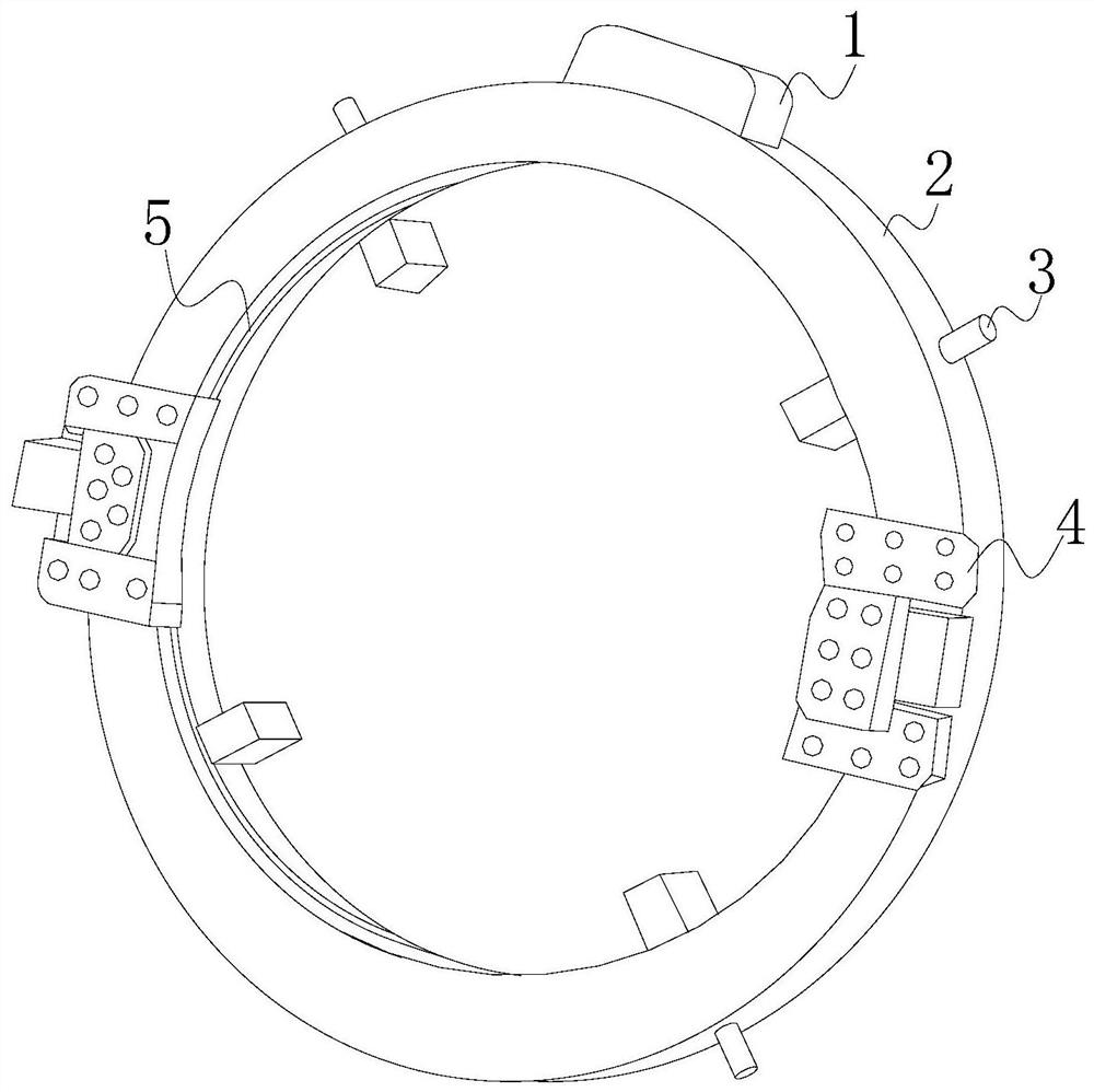
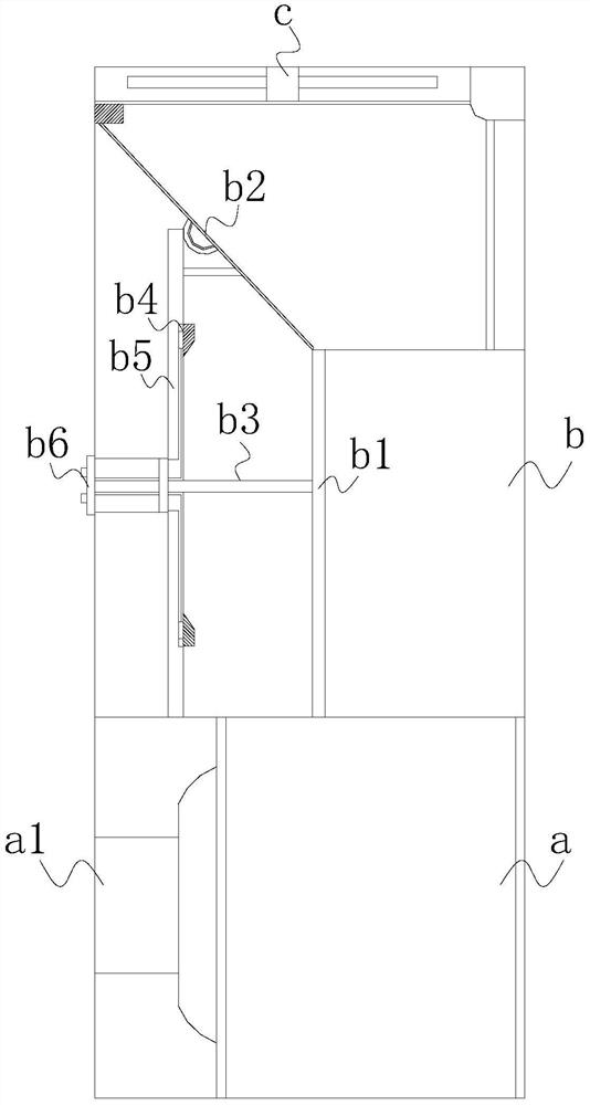
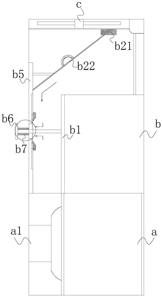
[0032] Such as Figure 1-Figure 7 As shown, the present invention provides a kind of external clip type cutting machine for pipe cutting, its structure includes driver 1, collar 2, fixture 3, clip 4, cutting slideway 5, and cutting slideway 5 is installed with cutting Knife, the cutting slideway 5 and the collar 2 are integrally formed, the clamp 3 is provided with four, and evenly mechanically connected to the collar 2 to cooperate with the pipeline, and the collar 2 is two equal semicircles The shape structure is fixed by the clip 4, the driving machine 1 is installed on the collar 2 to drive the cutting knife, the inside of the driving machine 1 is driven by the motor a, the motor a is fixed with the base a1, and the motor a is equipped with a vent b and a cooling fan c, and the vent b is provided with a first partition b1, a movable sloping plate b2, a connecting rod b3, a push-pull body b4, a second partition b5, a sealing member b6, a spring Axis b7, the first partition...


PUM


Abstract

The invention discloses an external blocking type cutter for pipeline cutting. The external blocking type cutter is characterized by structurally comprising a driver, a blocking ring, clamps, a blocking part and a cutting slide path, wherein a cutter is mounted in the cutting slide path; the cutting slide path is integrally formed with the blocking ring; the four clamps are uniformly and mechanically connected on the blocking ring, and are matched with pipelines; the blocking ring is formed by fixing two same semicircular structures through the blocking part; the driver is mounted on the blocking ring to drive the cutter; the inner part of the driver is driven by the motor; the motor is mounted and fixed through a pedestal; the motor is matched with a ventilation opening and a radiating fan, and a first partition plate, a movable inclined plate, a connecting rod, a pushing-pulling body, a second partition plate, a sealing part and a spring shaft are arranged in the ventilation opening;the movable inclined plate is mounted in the ventilation opening through a guide wheel, and can be movably in the form of a right trapezoid; a static inclined plate is closer to the radiating fan, sothat dust taken in can be adsorbed in a static mode, and therefore, taken-in dust is not greatly accumulated on the position, close to the motor, of the ventilation opening, and electrical harm is avoided.

Description

technical field [0001] The invention relates to the technical field of pipe cutting, in particular to an external card type cutting machine for pipe cutting. Background technique [0002] With the development of the modern mechanical processing industry, the requirements for the quality and precision of pipe cutting are constantly improving, and the requirements for improving production efficiency, reducing production costs, and having highly intelligent automatic cutting functions are also increasing. In on-site pipe processing, It is mainly a portable foreign card cutting beveling machine, which adopts hydraulic pressure and motor power. During the cutting process, the cutting machine is fixed on the pipe to be cut, and the cutting tool automatically rotates around the pipe for several weeks to cut off the pipe. Large volume, high efficiency, no burrs and no deformation in the cut. Since the motor used in this equipment is the driving force, good ventilation conditions for...

Claims


Application Information

Patent Timeline
Patent Type & Authority Patents(China)
IPC IPC(8): B23D21/00B23D33/00B23Q11/00
CPCB23D21/00B23D33/00B23Q11/005
Inventor 施卫杰
Owner SUZHOU YUANLIAN SCI & TECH PIONEER PARK MANAGEMENT CO LTD
Why Eureka
Try Eureka