Transmission shaft assembly mechanism of direct drive group assembly device

An assembly device and assembly mechanism technology, applied in the direction of assembly machines, metal processing equipment, metal processing, etc., can solve the problems of difficult automatic material absorption and assembly, and achieve the effect of fast conveying speed and high-precision assembly

Active Publication Date: 2021-05-14
深圳市睿荔科技有限公司
View PDF8 Cites 0 Cited by
  • Summary
  • Abstract
  • Description
  • Claims
  • Application Information

AI Technical Summary

Problems solved by technology

However, the transmission shaft has a slender structure as a whole, and it is difficult to automatically absorb materials and assemble through vacuum suction heads

Method used


Image

  • Transmission shaft assembly mechanism of direct drive group assembly device
  • Transmission shaft assembly mechanism of direct drive group assembly device
  • Transmission shaft assembly mechanism of direct drive group assembly device

Examples


Embodiment Construction

[0054] The present invention will be further described in detail below in conjunction with the accompanying drawings.

[0055] one

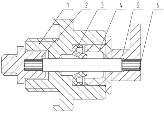
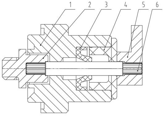
[0056] Such as figure 1 with figure 2 Shown: direct drive group, including drive shaft 6, bushing 1, dynamic seal structure, connecting piece 2 and lever 5;

[0057] The transmission shaft 6 is rotatably inserted in the sleeve 1; one axial end of the transmission shaft 6 is a transmission input end, and the other end is a transmission output end; the transmission input end is fixedly provided with the dial A rod 5, the shifting rod 5 has a shifting portion protruding outward along the radial direction of the transmission shaft 6; the transmission output end is coaxially fixed with the connecting piece 2;

[0058] The interior of the shaft sleeve 1 is provided with the dynamic sealing structure near the transmission input end, and the outer surface of the shaft sleeve 1 is provided with an assembly and fixing structure of the shaft sleeve 1 . ...


PUM


Abstract

The invention discloses a transmission shaft assembly mechanism of a direct transmission group assembly device, which is characterized in that it includes a vibrating plate for the transmission shaft, a first conveying pipe, a material receiving positioning seat for the transmission shaft, and a transplanting mechanism for the transmission shaft; The material-receiving positioning seat includes a base and a material-receiving assembly, and the material-receiving assembly includes a material-receiving bump, a material-receiving slider, a traverse cylinder for the material-receiving slider, and a jacking cylinder for the transmission shaft; the lower surface of the material-receiving slider and There is a jacking interval between the lower sides of the socket, and the height between the upper surface of the receiving slider and the lower side of the socket is consistent with the shaft length of the transmission shaft; the upper end of the first conveying pipe and the transmission shaft use a vibration plate The discharge port of the first delivery pipe is connected, and the lower end of the first conveying pipe is connected with the blanking hole on the material receiving bump. The transmission shaft assembly mechanism of the direct transmission group assembly device of the present invention has the advantages of being able to effectively ensure the orderly output and precise positioning of the transmission shafts one by one, and help realize high-precision assembly of the transmission shaft.

Description

technical field [0001] The invention belongs to the field of gas meters, and in particular relates to a transmission shaft assembly mechanism of a direct transmission group assembly device. Background technique [0002] The diaphragm gas meter is mainly composed of a metering part (including two metering boxes with flexible diaphragms inside each), a transmission part (including a diaphragm, a folding plate, a vertical shaft, a rocker arm, a connecting rod, a crank, a shift fork and a valve cover) ), the counting part and the housing. [0003] The working principle of the membrane gas meter is: a diaphragm (usually made of synthetic rubber) is sealed at the center line of each metering box, and the diaphragm divides the inside of the metering box into two metering gas chambers. After the gas enters the gas meter, it alternately enters the two metering gas chambers of each metering box, so that the diaphragm (and the diaphragm clamped on the diaphragm) reciprocate, and then ...

Claims


Application Information

Patent Timeline
Patent Type & Authority Patents(China)
IPC IPC(8): B23P21/00B23P19/00
CPCB23P19/004B23P21/006
Inventor 梁睿寇明林曾勇肖楠陈又吕东红罗丰华孙晏和张鹏白福川
Owner 深圳市睿荔科技有限公司
Why Eureka
Try Eureka