
A kind of sliding sleeve type sand blaster and using method

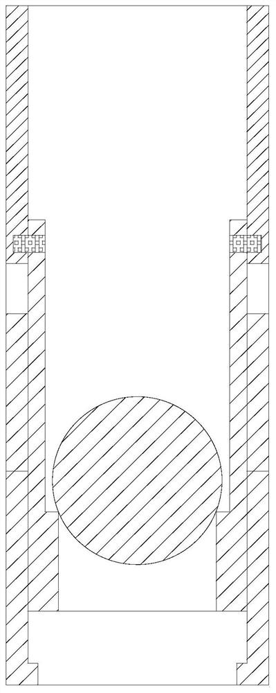
A technology of sand blaster and sliding sleeve, which is applied in the direction of earthwork drilling, wellbore/well components, production fluid, etc. It can solve the problems of improving equipment management and installation difficulty, so as to avoid oil and gas backflow from polluting the wellhead and sand particle velocity Evenly distributed and the effect of reducing the burden of pressure

Active Publication Date: 2021-12-14
宋伟杰
View PDF0 Cites 0 Cited by
  • Summary
  • Abstract
  • Description
  • Claims
  • Application Information

AI Technical Summary

Problems solved by technology

[0005] Furthermore, since the pitch decreases sequentially from top to bottom, the ball seat corresponding to the sand blaster also needs to gradually become smaller. When installing the sand blaster to the fracturing column, special attention must also be paid to the sequence, which improves equipment management. and installation difficulty

Method used


Image

  • A kind of sliding sleeve type sand blaster and using method
  • A kind of sliding sleeve type sand blaster and using method
  • A kind of sliding sleeve type sand blaster and using method

Examples


Embodiment Construction

[0030] Next, the technical solutions in the embodiments of the present invention will be described in connection with the drawings of the embodiments of the present invention, and it is understood that the described embodiments are merely the embodiments of the present invention, not all of the embodiments. Based on the embodiments of the present invention, all other embodiments obtained by those of ordinary skill in the art are in the range of the present invention without making creative labor premise.

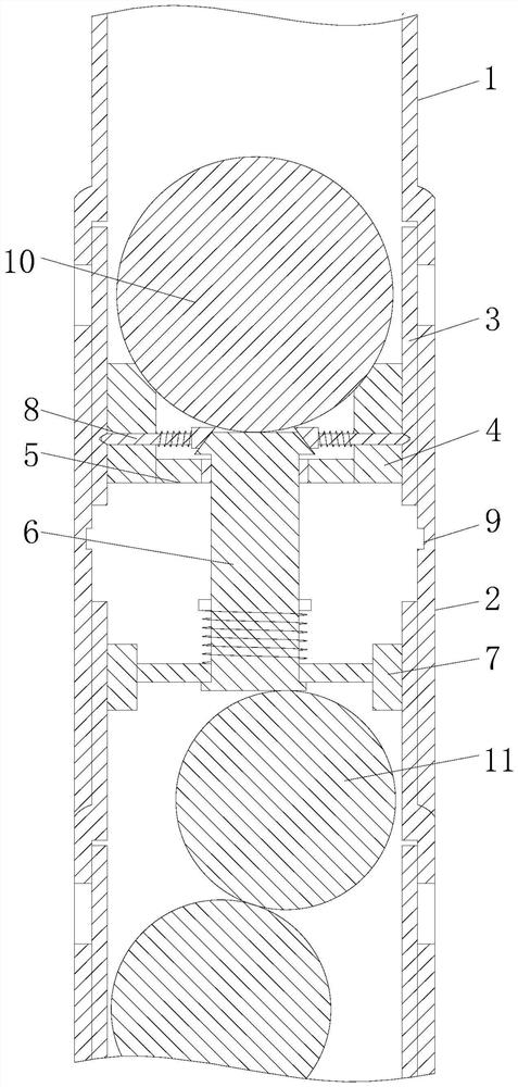
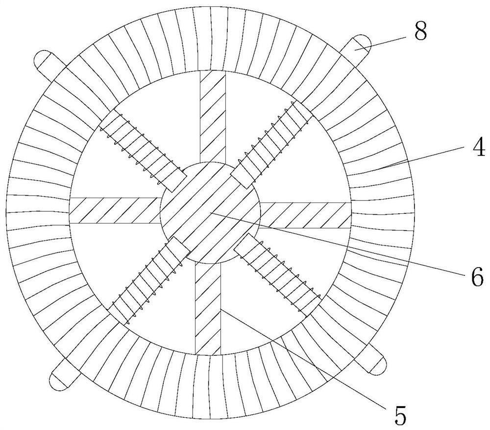
[0031] See Figure 2-5 A slip-blasting, comprising the stub 1, to take over the sleeve 2 and 3, the nozzle 4, the slider 4 slides the ball seat at a predetermined position 1 and 2 to take over the internal slide slidably provided with a ball seat corresponding sliding sleeve 3 is connected to drive the sliding sleeve 3 moves and pitching and plugging with lower pipe 10, the sliding central ball seat 4 is provided with a through hole 5, the through hole 5 to ensure that the ball s...


PUM


Abstract

The invention relates to the technical field of oil exploitation equipment, and discloses a sliding sleeve type sand blaster, which includes an upper connecting pipe, a lower connecting pipe and a sliding sleeve, and a freely sliding sliding ball seat is arranged inside the upper connecting pipe and the lower connecting pipe. The sliding sleeve sand blaster and its use method, because the sliding ball seats are put in step by step, the diameters above the sliding ball seats of the fracturing stages are exactly the same, the distribution of the flow section in the fracturing column is even, and no large pressure will be generated Reduce the pressure burden on the pump station and pipe string, and the water flow velocity is higher, the sand particle velocity distribution is more uniform, and the nozzle wear distribution is relatively uniform. At the same time, the sandblasting machine uses the same diameter of the ball, and the management and operation are relatively simple. Secondly, the two-way sealing of the ball can avoid oil and gas backflow from polluting the wellhead. Finally, because the sand blasters installed at each stage are exactly the same, the management and installation of the sand blasters are also simpler, and the models of the production process are relatively reduced.

Description

Technical field [0001] The present invention relates to the technical field of oil exploration equipment, particularly as a sleeve-type blasting device and methods of use. Background technique [0002] See figure 1 , As a sleeve-type sandblasting, when the sliding sleeve is opened by sand blasting using pitching hold lamination method, sand blasting Kongkai Qi, so that the jet reservoir and the high cracks. [0003] In order to make the pitching into the target layer, layer by layer from top to bottom between the reduced diameter and the pitch corresponding to the sealing ball seat, on the one hand, that the flow diameter of the inner tube layer by layer reduction, since the lowermost end of the flow diameter is too small, is not achieved displacement injection, and the injection pressure in order to ensure the lower end of the pump station require higher pumping pressures, and the pressure of the pressure pipe system is also greater, reducing its service life, further, in the ca...

Claims


Application Information

Patent Timeline
Patent Type & Authority Patents(China)
IPC IPC(8): E21B43/267
CPCE21B43/267
Inventor 杨敏
Owner 宋伟杰
Learn More