Shock absorbing device for electromechanical equipment

A technology of shock absorbing device and electromechanical equipment, which is applied in the direction of mechanical equipment, spring/shock absorber, vibration suppression adjustment, etc., can solve the problems of weakened shock absorption effect and inconvenient promotion and implementation, and achieve strong applicability and easy promotion and implementation , good shock absorption effect

Active Publication Date: 2021-08-17
郑州盛泰恒鑫数据科技有限公司
View PDF8 Cites 1 Cited by
  • Summary
  • Abstract
  • Description
  • Claims
  • Application Information

AI Technical Summary

Problems solved by technology

The vibration damping device of the electromechanical equipment is connected through the air cylinder, and the air cylinder has a supporting function, which leads to the weakening of the shock absorption effect, which is not convenient for popularization and implementation

Method used


Image

  • Shock absorbing device for electromechanical equipment
  • Shock absorbing device for electromechanical equipment
  • Shock absorbing device for electromechanical equipment

Examples


Embodiment 1

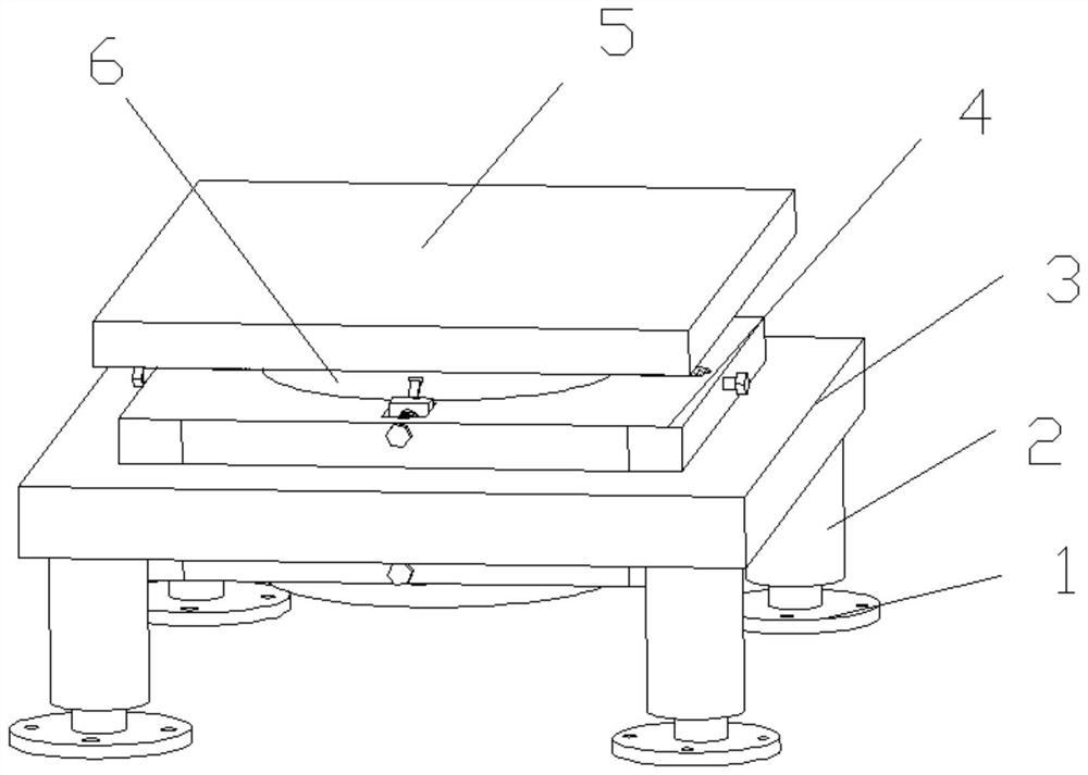
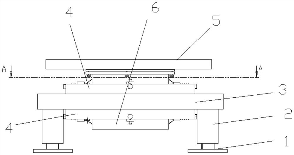
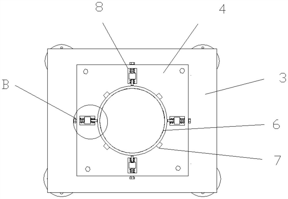
[0026] see Figure 1-4 , a shock absorbing device for electromechanical equipment, including a workbench 3 and an installation platform 5, the middle position of the workbench 3 is provided with a hollow, the upper and lower surfaces of the workbench 3 are fixedly installed with a fixing plate 4, and the center position of the lower surface of the installation platform 5 is A vertical support column 6 is fixedly connected, and the support column 6 passes through the workbench 3 and the fixed plate 4 . The support column 6 is a cylindrical structure, thereby facilitating the installation of the device. The support column 6 is a hollow structure, thereby reducing the weight of the device and saving manufacturing materials. A plurality of sliding grooves 8 are provided on the fixed plate 4, and the sliding grooves 8 are located around the support column. The sliding block 9 and the moving block 11 are slidably placed inside the sliding groove 8, and the moving block 11 is provid...

Embodiment 2

[0031] see Figure 5 , on the basis of Embodiment 1, the supporting foot 1 includes a nesting groove 17, a fixed plate 22 and a threaded rod 20, and the bottom of the supporting leg 2 includes upper and lower parts, and the upper and lower parts are detachably connected by a flange 24 , so as to facilitate the installation of the supporting foot 1. The inside of the nesting groove 17 can be nested with a second nut 19 which can be raised and lowered. The nesting groove 17 is a polygonal column structure, thereby preventing the second nut 19 from rotating inside the nesting groove 17, and the second nut 19 is nested on the threaded rod 20. Two springs 18, the second spring 18 is located below the supporting leg 2, twisting the threaded rod 20 can make the threaded rod 20 rise and fall at the bottom of the supporting leg 2, thereby adjusting the length of the threaded rod 20, thereby adjusting the compression amount of the second spring 18 to Controls the damping strength. The...


PUM


Abstract

The invention relates to the technical field of electromechanical equipment, and specifically discloses a shock absorbing device for electromechanical equipment, which includes a workbench and an installation platform. Fixing plates are fixedly installed on the upper and lower surfaces of the workbench, and support columns are connected to the bottom of the installation platform, and the support columns pass through the Through the workbench and the fixed plate, there are several sliding grooves on the fixed plate around the support column. The sliding block and the moving block are placed inside the sliding groove. The moving block is provided with two sliding blocks placed on both sides of the sliding block. Inside the groove, the two ends of the fastening bolt are provided with opposite threads, the moving block is threadedly connected to the two ends of the fastening bolt, and the first spring is nested on the fastening bolt between the sliding block and the moving block; the sliding block passes through The connecting rod is rotatably connected to the outer wall of the supporting column, and the four corners of the lower surface of the workbench are fixedly provided with supporting legs. The invention has the advantages of simple structure, convenient assembly, good shock absorption effect, stable support, strong applicability, and convenient popularization and implementation.

Description

technical field [0001] The invention relates to the technical field of electromechanical equipment, in particular to a vibration damping device for electromechanical equipment. Background technique [0002] With the rapid development of China's manufacturing industry, the electromechanical equipment required by the manufacturing industry is also developing towards large-scale and heavy weight. In most cases, large-scale electromechanical equipment is placed directly on the ground, and its bottom is generally in direct contact with the ground. Or simply add spacers under the tripod, the purpose of which is to prevent the machine tool from crushing and fracturing the ground. The shock absorption of existing mechanical equipment or the protection measures for contact with the ground are too simple and the effect is not good. For machines that generate strong vibration, simple shock absorbers will not play any substantial role. The shock absorber is installed under the base of m...

Claims


Application Information

Patent Timeline
Patent Type & Authority Patents(China)
IPC IPC(8): F16F15/08
CPCF16F15/085
Inventor 丁丹刘成恩魏海明黄先刚
Owner 郑州盛泰恒鑫数据科技有限公司
Why Eureka
Try Eureka