
Seal for sealing a peripheral gap between two machine components

A technology of machine parts and seals, which is applied in the field of seals used to seal the circumferential gap between two machine parts, can solve problems such as blocking auxiliary sealing systems, reduce complexity, reduce subsequent processing, and reduce testing The effect of times

Active Publication Date: 2020-02-18
SIEMENS ENERGY GLOBAL GMBH & CO KG
View PDF8 Cites 2 Cited by
  • Summary
  • Abstract
  • Description
  • Claims
  • Application Information

AI Technical Summary

Problems solved by technology

This results in a very high manufacturing precision that must be guaranteed, while misalignment of components due to manufacturing precision and temperature effects can block the secondary sealing system, so that the corresponding lamellae of the secondary seal cannot completely close the open axial gap in the direction of the shoe as required

Method used


Image

  • Seal for sealing a peripheral gap between two machine components
  • Seal for sealing a peripheral gap between two machine components
  • Seal for sealing a peripheral gap between two machine components

Examples


Embodiment Construction

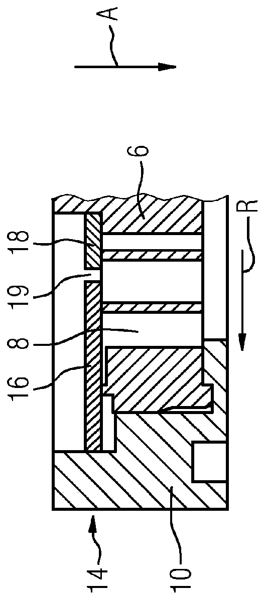
[0033] figure 1 A part of a seal 2 is shown, which is used to seal a circumferential gap between two machine parts (not shown here in detail), which can rotate axially relative to each other. The axial direction is symbolically identified by point A, which is intended to represent the center of the circle formed by the complete seal 2 , although the pitch ratio is not maintained in the figure. figure 1 Radial R and circumferential U are also shown.

[0034] The seal 2 comprises a main seal 4 having a plurality of so-called shoes 6 for creating a contact-free seal between machine parts. To enable this function, the boots 6 are each elastically mounted on the carrier 10 via a spring element 8 . The shoe 6 is supported on a machine part by the bracket 10 so that radial movement of the shoe can be made in response to fluid pressure applied to the shoe 6 .

[0035] Furthermore, the seal 2 comprises a layered auxiliary seal 12 which seals the spring element 8 in the axial direction...


PUM


Abstract

The invention relates to a seal comprising: a main seal having a shoe establishing a contactless seal between machine components and a spring element supporting the shoe on the machine components suchthat a radial movement of the shoe acts as a reaction to a fluid pressure applied to the shoe; and an auxiliary seal sealing the spring element in the axial direction, the auxiliary seal having at least two layers adjacent to each other in the axial direction. In order to improve the functional reliability, the layers each comprise at least two sheets which are positioned radially next to each other; for each layer, one sheet is fixed and the other sheet is movable by being fixed on the shoe; seen from the radial direction, the two moving sheets of every two directly adjacent layers have different widths, the wider one of the two moving sheets is combined with the narrower fixed sheet to form a layer, and the narrower one of the two moving sheets is combined with the wider fixed sheet toform a layer; and the wider moving sheet in one layer is overlapped with the wider fixed sheet in the corresponding other layer in the radial direction.

Description

technical field [0001] The invention relates to a seal for sealing a circumferential gap between two machine parts, one of which is axially rotatably mounted relative to the other machine part, the seal comprising: a main seal having At least one shoe for establishing a contactless seal between machine parts and having at least one spring element supporting the shoe on a machine part such that radial movement of the shoe acts as a countermeasure against fluid applied to the shoe a pressure response; and an auxiliary seal axially sealing the spring element, wherein the auxiliary seal has at least two layers axially adjacent to each other. Background technique [0002] Such seals are known, for example, from publication US 2008 / 100000 A1. The seal serves in particular to seal the gap between the rotor and the housing of the turbomachine. [0003] The seal described above has the advantage that the sealing gap is adjusted by the volume flow acting on the seal, so that the sea...

Claims


Application Information

Patent Timeline
Patent Type & Authority Applications(China)
IPC IPC(8): F16J15/16
CPCF16J15/16F16J15/442
Inventor P·希曼斯基F·蒂多纳
Owner SIEMENS ENERGY GLOBAL GMBH & CO KG
Learn More