A state-of-charge balance control method for parallel multi-energy storage in isolated DC microgrid
A technology of DC microgrid and state of charge, applied in the direction of AC network load balancing, etc., can solve problems such as line mismatch, poor stability, and complex control system, so as to improve service life, improve distribution accuracy, and avoid excessive charging and discharging. Effect
- Summary
- Abstract
- Description
- Claims
- Application Information
AI Technical Summary
Problems solved by technology
Method used
Image
Examples
Embodiment 1
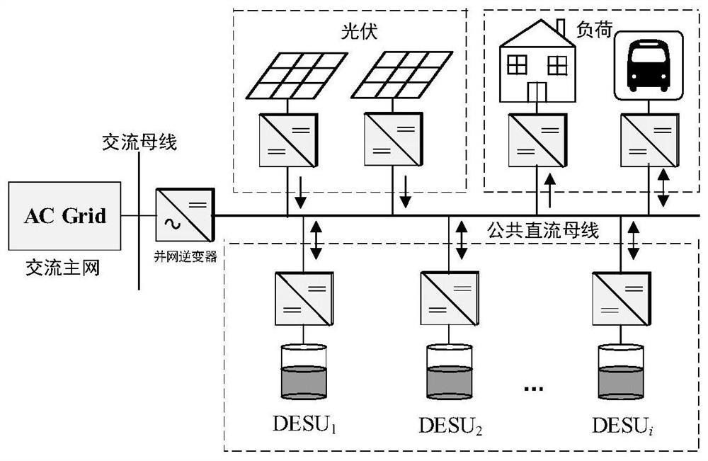
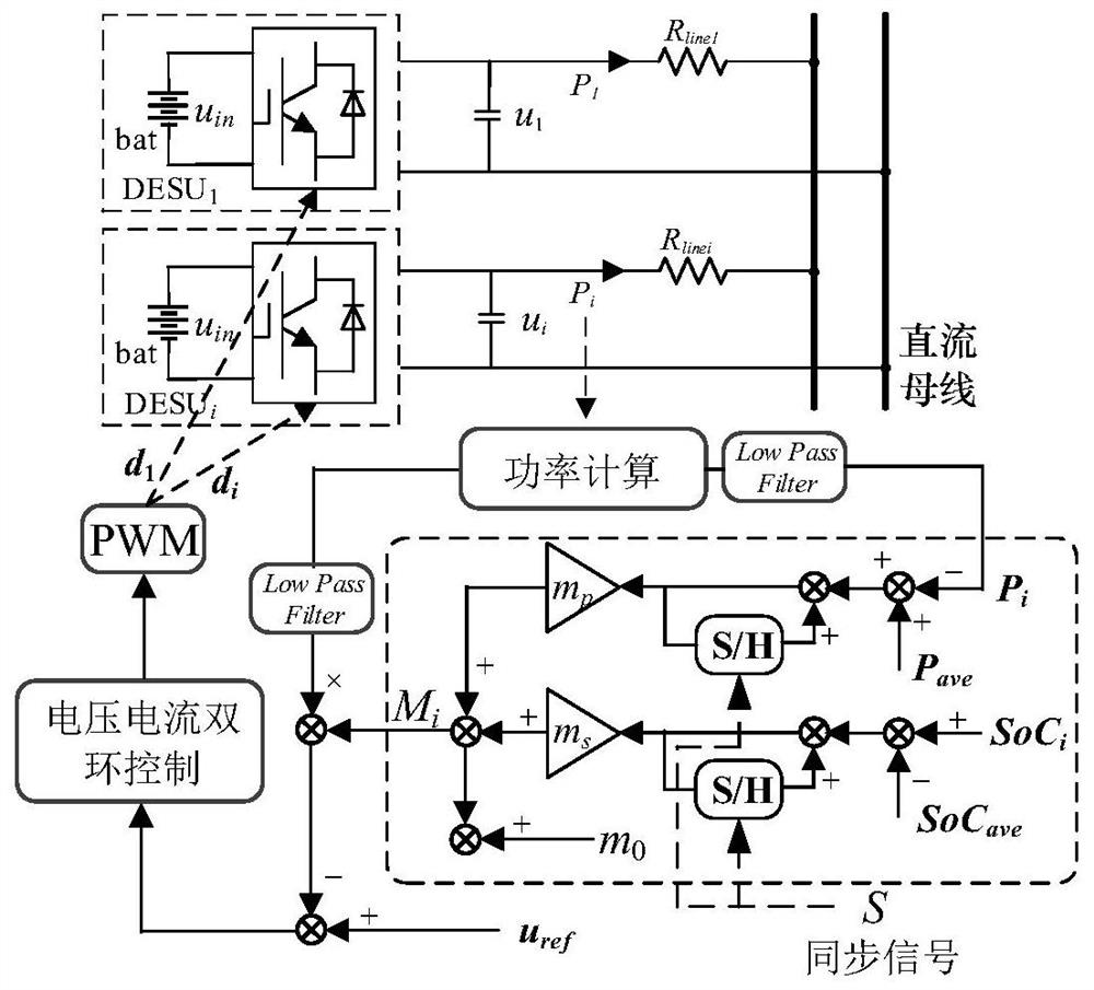
[0080]Based on the RTDS platform, build an isolated island DC microgrid system with three sets of parallel distributed energy storage units, including the first energy storage unit, the second energy storage unit and the third energy storage unit. The capacity of the energy storage unit is set to 12Ah, and other details of the system The control parameters are shown in Table 1:
[0081] Table 1 System experiment parameters based on RTDS platform
[0082]
[0083] The initial state of charge of each energy storage unit is set to be 80%. When the output power of the photovoltaic system cannot meet the power demanded by the load, in order to maintain the real-time power balance in the microgrid, the energy storage system is in a stable discharge state at this time, and its experimental waveform is shown in Figure 6(a); The energy units all operate in the traditional droop control method, as shown in Figure 6(b), due to the influence of the mismatched line impedance, the load ...
Embodiment 2
[0087] The configuration of the energy storage unit group is the same as that in Embodiment 1. As shown in Figure 8(a), the energy storage system is in a stable charging state from 0 to 8s, and operates in the traditional droop control method before 4s. The improved droop control method proposed in the present invention, the corresponding state of charge begins to converge, and the photovoltaic system is affected by external factors at 8s, resulting in a reduction in output power, and the photovoltaic power generation cannot meet the load power demand, as shown in Figure 8(b). When the power fluctuates, the energy storage system quickly switches from the charging state to the discharging state. It can be clearly observed from Figure 8(a) that under the improved droop control method proposed in the present invention, even if the photovoltaic power fluctuates, the charging state is still at Gradually balance the state, and finally reach the state of charge balance. As shown in F...
Embodiment 3
[0089] The configuration of the energy storage unit group is the same as that in Embodiment 1. As shown in Figure 9(a), from 0 to 8s, the energy storage system is in a stable discharge state, before 4s it operates in the traditional droop control method, and at 4s the energy storage unit switches to In the improved droop control method proposed by the present invention, the corresponding state of charge begins to converge, and the load power demand suddenly decreases at 8s. At this time, the photovoltaic power generation power still remains after meeting the load power demand, as shown in Figure 9(b). The energy storage system quickly switches from the discharge state to the charge state, as shown in Figure 9(a), under the improved droop control method proposed in the present invention, load power fluctuations will not affect the state of charge balance control effect between energy storage units. As shown in Figure 9(c), under the improved droop control method proposed by the ...
PUM
 Abstract
Description
Claims
Application Information
 - R&D
- Intellectual Property
- Life Sciences
- Materials
- Tech Scout
- Unparalleled Data Quality
- Higher Quality Content
- 60% Fewer Hallucinations
Browse by: Latest US Patents, China's latest patents, Technical Efficacy Thesaurus, Application Domain, Technology Topic, Popular Technical Reports.
© 2025 PatSnap. All rights reserved.Legal|Privacy policy|Modern Slavery Act Transparency Statement|Sitemap|About US| Contact US: help@patsnap.com


