Positioning system

A positioning system and specific technology, applied in the field of positioning systems, can solve problems such as increasing errors, and achieve the effects of reducing overall delay, simplifying identification algorithms, and simplifying identification

Inactive Publication Date: 2020-02-18
虚拟软件2007股份公司 +1
View PDF5 Cites 2 Cited by
  • Summary
  • Abstract
  • Description
  • Claims
  • Application Information

AI Technical Summary

Problems solved by technology

[0012] ●It requires the history control to be synchronized with the turn on of the LED, which increases the possibility of error

Method used


Image

  • Positioning system
  • Positioning system
  • Positioning system

Examples


Embodiment Construction

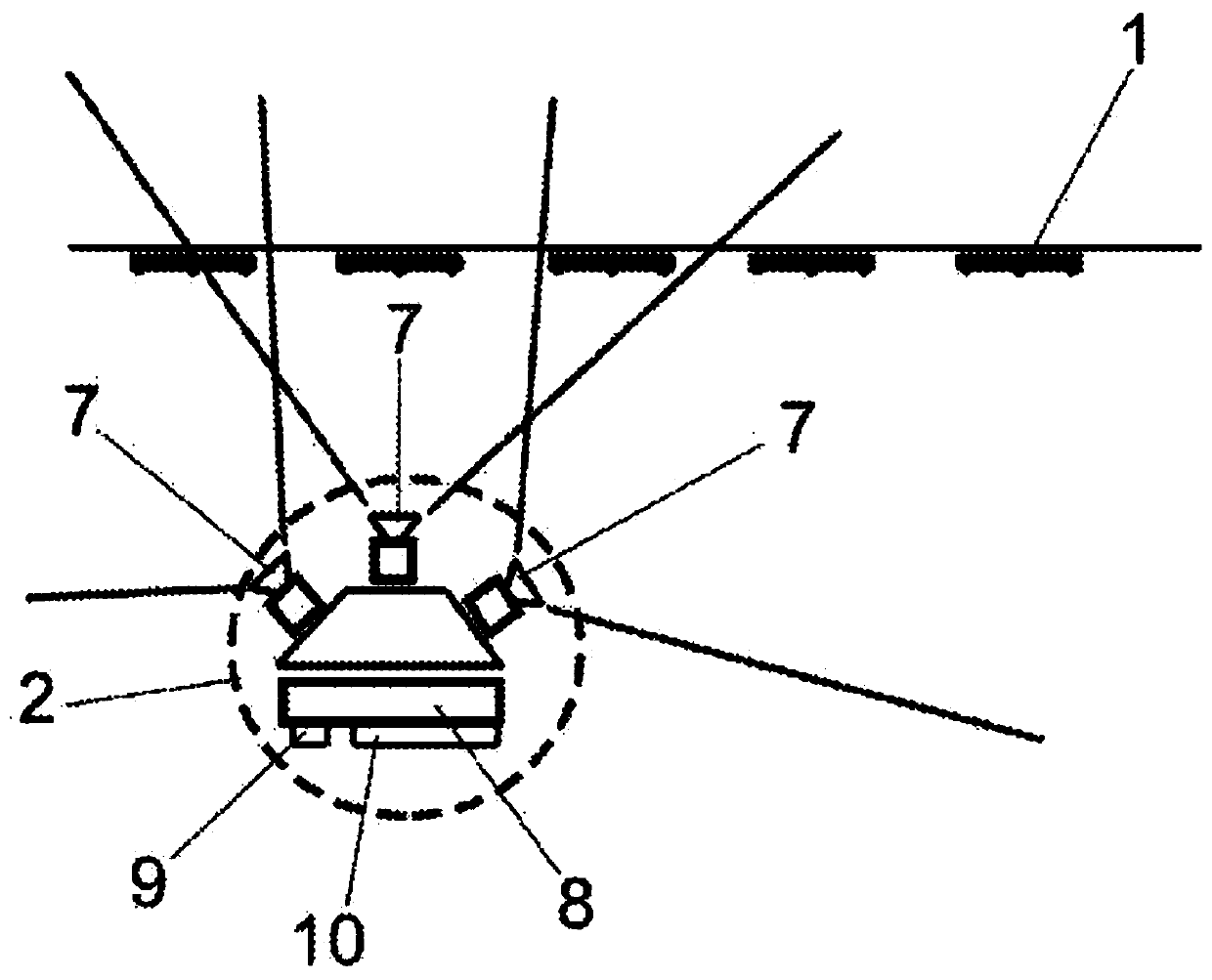
[0058] From the preceding figures, it can be seen how the inventive positioning system for virtual reality objects consists of two basic elements: a series of spatial modules (1), which are static and conveniently distributed on top of the operating surface; and A series of tracking devices (2) associated with each player or user.

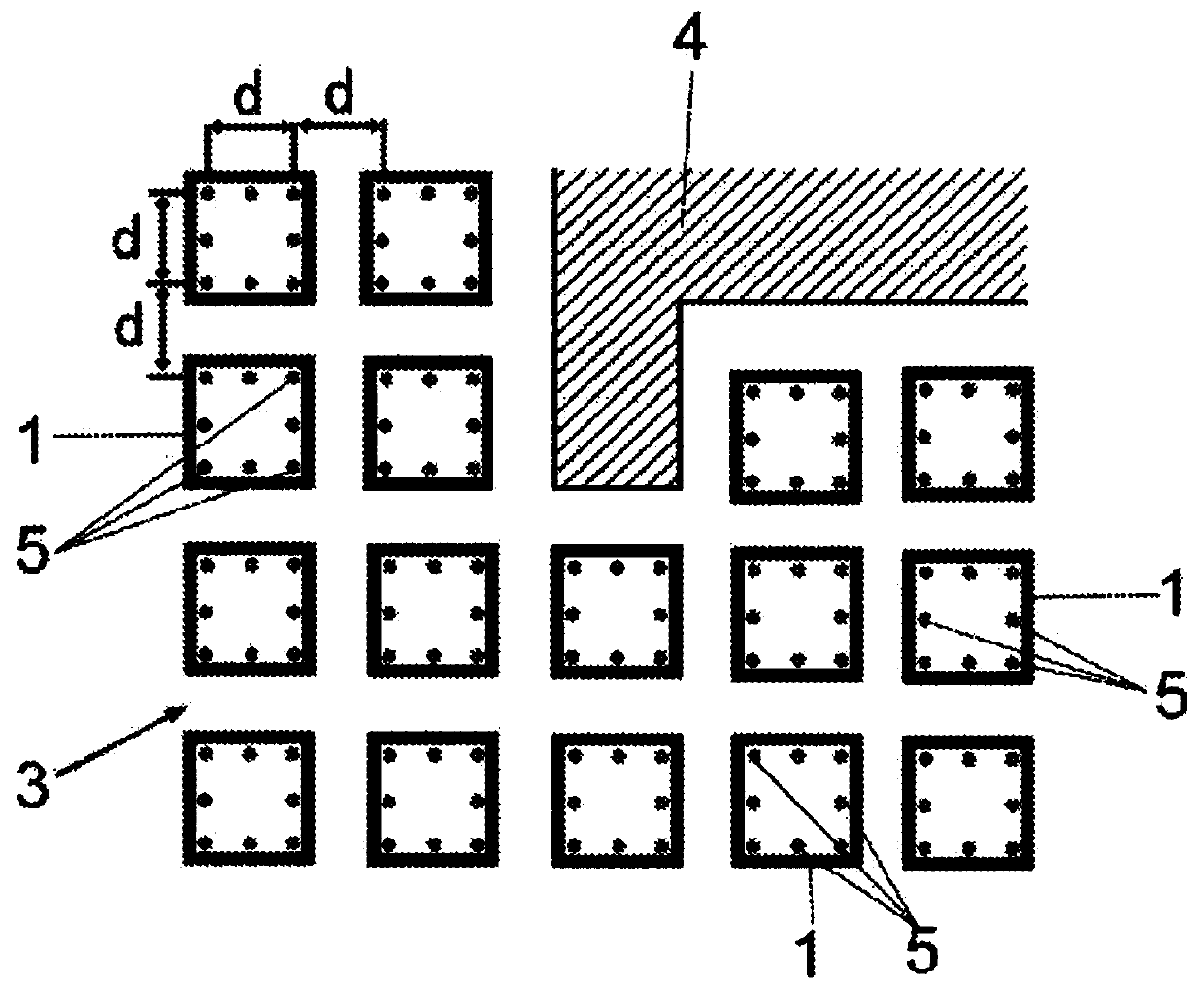
[0059] like image 3 As shown, it is conceivable that, in plan view, the interaction space (3) or absolute reference system is divided into a series of equidistant, adjacent partitions or segments, in each partition or segment a spatial module (1) is arranged , so that the space modules are all arranged equidistantly at a distance (d), adapting to in-situ irregularities (4) that the interaction space (3) may have.

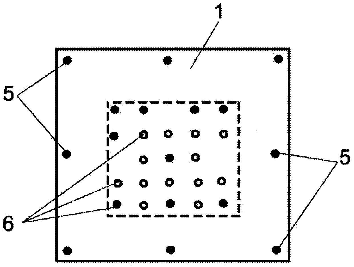
[0060] according to figure 2 , the space module (1) is made of a square panel in which two sets of LEDs of different types are integrated.

[0061] More specifically, a series of reference LEDs (5) and a series of identification LED...


PUM


Abstract

Especially designed for large covered spaces, the system is made up of a series of conveniently distributed static spatial modules (1) and a series of tracking units (2), associated with each player or user, so that the spatial modules (1) are formed by a square panel, in which two groups of LED diodes of different types of visible spectrum reference LEDs (5) and infrared identification LEDs (6) are integrated, each spatial module (1) including configuration means for its identification diodes (6) as well as power supply means or means for connecting to a power supply. Simultaneously, the tracking units (2) include a series of cameras (7) with different orientations, associated with an image-processing unit (8), having a communications port (9) and electrical power supply means (10). The system is complemented by software for processing the information sent and previously managed by the tracking units, which can be implemented indistinctly via the processing unit associated with each tracking unit or in a more powerful external processing unit, via a communication network.

Description

technical field [0001] The present invention relates to a positioning system, more particularly for locating objects in different types of spaces for multiple applications. [0002] It is an object of the present invention to provide a positioning system that can be effectively applied in closed spaces without creating "dead zones" due to the presence of obstacles such as columns, corridors, etc., and without user restrictions. Background technique [0003] Until now, in some existing positioning systems there were several cameras, which were positioned in the operating space involved, so that each user of the system had a helmet, glasses or a similar element in which one or more identification LEDs were arranged, The identification LED is identified by the aforementioned camera by means of corresponding identification software, so that the identification cannot be performed when the operating space includes obstacles (such as columns, partitions, corridors, etc.) that hinde...

Claims


Application Information

Patent Timeline
Patent Type & Authority Applications(China)
IPC IPC(8): G06F3/00G01S5/16G01C21/00G06T19/00
CPCG01C21/206G01S5/16G06F3/012G06F3/0325G06T19/006G06F3/017A63F13/213A63F13/211A63F13/212A63F13/25A63F13/428A63F13/5255G06F3/011
Inventor 哈维尔·伊巴内斯·克鲁赛罗
Owner 虚拟软件2007股份公司
Why Eureka
Try Eureka