Multifunctional sand making machine convenient to use

A sand making machine, multi-functional technology, applied in cleaning methods and utensils, removal of smoke and dust, grain processing, etc., can solve the problems affecting users' experience of using the sand making machine, poor crushing effect, etc., achieve good dust removal function, convenient movement , the effect of simple structure

Inactive Publication Date: 2020-02-21
ZAOZHUANG SNKSAN INTELLIGENT MACHINERY CO LTD
View PDF7 Cites 5 Cited by
  • Summary
  • Abstract
  • Description
  • Claims
  • Application Information

AI Technical Summary

Problems solved by technology

[0004] However, due to the relatively simple structure of the sand making machine, the crushing effect of the sand making machine on materials is poor, and a large amount of dust will be scattered when the sand making machine is in use, and the scattering of dust will affect the use of the sand making machine by users. to experience

Method used


Image

  • Multifunctional sand making machine convenient to use
  • Multifunctional sand making machine convenient to use
  • Multifunctional sand making machine convenient to use

Examples


Embodiment 1

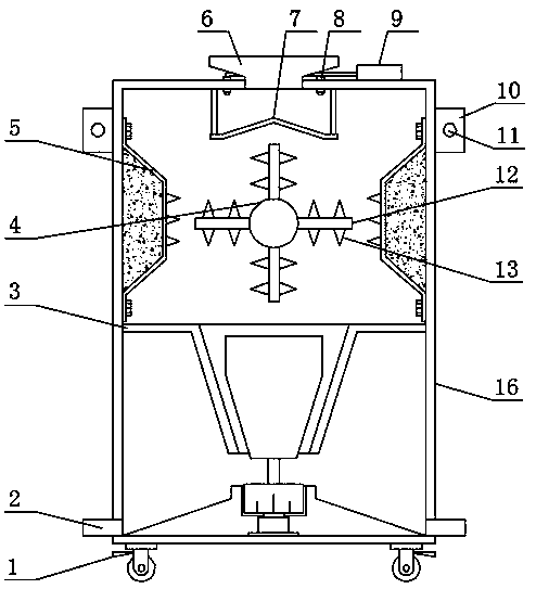
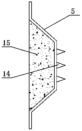
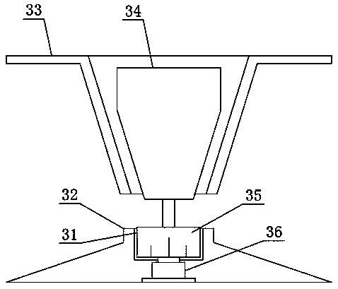
[0021] see Figure 1-Figure 4 , the present invention provides a technical solution: an easy-to-use multifunctional sand making machine, including a body 16, a feed hopper 6 is welded on the upper surface of the body 16, a discharge pipe 2 is welded on both sides of the body 16, and the body 16 The top of the rotor 4 is provided with a rotor 4. The use of the rotor 4 is an existing technology. The outer side of the rotor 4 is welded with a broken part 12. The two sides of the broken part 12 are provided with integrally formed first broken teeth 13. The inner wall of the body 16 is provided with a The crushing plate 5 corresponding to the broken piece 12, the protective plate 7 is arranged under the feeding hopper 6, the nozzle 8 is arranged on both sides of the feeding hopper 6, and the water pump corresponding to the nozzle 8 is welded on one end of the upper surface of the body 16 9;

[0022] In order to enrich the functions of the crushing plate 5, in this embodiment, pref...

Embodiment 2

[0027] On the basis of Embodiment 1, in order to make the hoisting of the sand making machine more convenient, in this embodiment, preferably, the top of the body 16 is provided with a hanging plate 10, the hanging plate 10 is a cuboid structure, and the hanging plate 10 and The body 16 is fixedly connected by welding, and one end of the hanging plate 10 is provided with a hanging hole 11. When in use, the hook on the lifting equipment is passed through the hanging hole 11, and then the sand making machine is hoisted by the lifting equipment to solve the problem. The problem of inconvenient hoisting of the traditional sand making machine is solved;

[0028] In order to make the movement of the sand making machine more convenient, in this embodiment, preferably, the two ends of the lower surface of the body 16 are provided with ground wheels 1, and the ground wheels 1 are universal wheels with self-locking function. The body 16 is fixedly connected by welding, and the sand maki...


PUM


Abstract

The invention discloses a multifunctional sand making machine convenient to use, and belongs to the technical field of sand making machines. The multifunctional sand making machine comprises a machinebody. A feeding hopper is arranged on the upper surface of the machine body. Discharging pipes are arranged on the two sides of the machine body. A rotor is arranged at the top end of the machine body. A crushing part is arranged on the outer side of the rotor. First crushing teeth are arranged on the two sides of the crushing part. A crushing plate corresponding to the crushing part is arrangedon the inner wall of the machine body. A protective plate is arranged below the feeding hopper. Spray heads are arranged on two sides of the feeding hopper. Water pumps corresponding to the spray heads are arranged at one end of the upper surface of the machine body. The multifunctional sand making machine is simple in structure and convenient to use. Materials can be crushed by a plurality of times during use, so that the crushing effect of the sand making machine on the materials is better. Moreover, the multifunctional sand making machine has a good dust removing function, and can effectively prevent a large amount of dust from flying out during use of the sand making machine, and therefore a better sand making machine use experience is brought to a user.

Description

technical field [0001] The invention belongs to the technical field of sand making machines, and in particular relates to an easy-to-use multifunctional sand making machine. Background technique [0002] The Chinese patent (publication number is CN208661370U) discloses a graded crushing fine sand making machine, including a body, a feeding mechanism, a primary crushing mechanism and a secondary crushing mechanism. The primary crushing mechanism consists of a first crushing knife, a second crushing knife, a crushing roller and a motor. [0003] The advantage of this graded crushing fine sand making machine is that by setting the feeding channel, fine material channel and filter screen one, the raw materials can be graded and screened before entering the graded crushing fine sand making machine. The channel enters the first-stage crushing mechanism, and the smaller blocky fine materials enter the fine material channel from the filter screen one, and then fall into the seconda...

Claims


Application Information

Patent Timeline
Patent Type & Authority Applications(China)
IPC IPC(8): B02C21/02B02C18/14B02C2/10B02C23/04B08B15/04
CPCB02C2/10B02C18/14B02C21/02B02C23/04B08B15/04
Inventor 马驰孙启祥孙法虎
Owner ZAOZHUANG SNKSAN INTELLIGENT MACHINERY CO LTD
Why Eureka
Try Eureka