Bending device for producing filter

A bending device and filter technology, applied in the direction of feeding device, positioning device, storage device, etc., can solve the problems of many defective products, the device cannot control the bending position, etc., so as to improve the bending quality and reduce labor intensity and production costs, the effect of improving accuracy

Active Publication Date: 2020-02-21
LEIYANG YAXIANG ELECTRONICS TECH
View PDF7 Cites 2 Cited by
  • Summary
  • Abstract
  • Description
  • Claims
  • Application Information

AI Technical Summary

Problems solved by technology

[0004] However, the above-mentioned device cannot control the bending position, resulting in many defective products after bending. Therefore, in view of the above status quo, it is urgent to develop a bending device for filter production to overcome the shortcomings in current practical applications.

Method used


Image

  • Bending device for producing filter
  • Bending device for producing filter
  • Bending device for producing filter

Examples


Embodiment 1

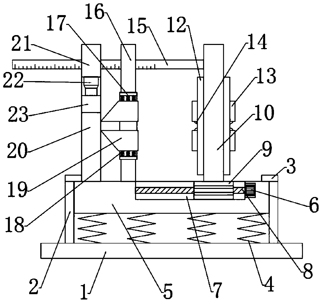
[0026] See Figure 1-4 In the embodiment of the present invention, a bending device for filter production includes a base 1, a movable plate 4 is provided on the upper side of the base 1, and a shock absorption mechanism is provided between the movable plate 4 and the base 1, so A chute 7 is provided on the top of the movable plate 4, and a feeding mechanism is slidably connected to the chute 7, and a bending mechanism fixedly connected to the movable plate 4 is provided on the left side of the feeding mechanism. The bending mechanism is connected with the feeding mechanism. A reinforcement mechanism is arranged between the mechanisms.

Embodiment 2

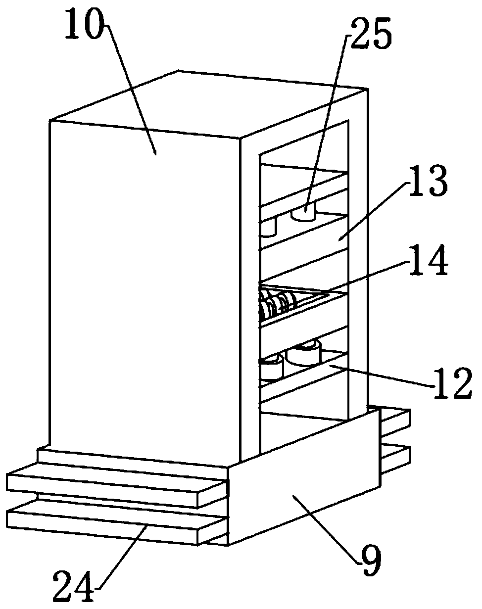
[0028] In this embodiment, the feeding mechanism includes a slider 9, which is slidably connected to the inside of the chute 7. The slider 9 and the movable plate 5 are connected by a driving mechanism, and the top of the slider 9 is fixedly connected A fixed block 10 is provided. The inner side of the fixed block 10 is fixedly connected with a fixed frame 12, the upper and lower ends of the inner side of the fixed frame 12 are fixedly connected with a second telescopic rod 25, and the other end of the second telescopic rod 25 is connected to The pressure plate 13 is connected. A number of electric rollers 14 are rotatably connected to the inside of the pressure plate 13, and a ruler 15 is fixedly connected to the left side of the fixed block 10. By setting a feeding mechanism, the transportation of raw materials can be realized, which improves work efficiency and reduces The labor intensity and production cost are reduced, and the raw materials can be fixed by setting the secon...


PUM


Abstract

The invention relates to the field of filter production, in particular to a bending device for producing a filer. The bending device comprises a base, and a movable plate is arranged on the upper sideof the base. A damping mechanism is arranged between the movable plate and the base, and a sliding groove is formed in the top end of the movable plate. A conveying mechanism is arranged on the sliding groove in a sliding connecting manner. A bending mechanism fixedly connected with the movable plate is arranged on the left side of the conveying mechanism. A reinforcing mechanism is arranged between the bending mechanism and the conveying mechanism. According to the bending device, by arranging the conveying mechanism, transportation of raw materials can be achieved, the work efficiency is improved, and meanwhile the labor intensity and the production cost are reduced; by arranging a driving mechanism, the moving distance of a sliding block can be accurately controlled; in cooperation with a scaleplate, the bending position can be accurately controlled; and by arranging the reinforcing mechanism, a pull rope can drive clamping plates on the two sides to move towards the materials while a pressing block moves downwards, and therefore the materials are further fixed, and the product quality is effectively guaranteed.

Description

Technical field [0001] The invention relates to the field of filter production, in particular to a bending device for filter production. Background technique [0002] Electricity is an energy source that uses electric energy as power. It converts the primary energy of the natural world into electricity through mechanical energy devices, and then supplies the electricity to users through power transmission, transformation and distribution. Filters, power transmission and distribution systems operate under fixed frequency sine wave voltage and current waveforms, but when nonlinear loads such as thyristor rectifiers, inverters and electric arc furnaces are connected to the system, a large amount of harmonic currents will be generated. This leads to distortion of voltage and current, and harmonic filters are the best way to suppress the distortion of voltage and current of the grid. [0003] Chinese Patent (Authorized Announcement Number: CN 202930527 U) discloses a bending mechanism...

Claims


Application Information

Patent Timeline
IPC IPC(8): B21D7/06B21D7/14B21D7/16B21D43/00B21D43/13B21F1/00B21F23/00H01P11/00
CPCB21D7/06B21D7/14B21D7/16B21D43/003B21D43/13B21F1/006B21F23/00H01P11/00H01P11/001
Inventor 陈小勇杨艳军
Owner LEIYANG YAXIANG ELECTRONICS TECH
Why Eureka
Try Eureka