
Suspension train car end connection method and system

A connection system and vehicle-end technology, which is applied to elevated railway systems, motor vehicles, and railway vehicles with suspended vehicles, can solve problems such as poor stability of suspended train passages, meet dynamic performance, and improve comfort , to ensure the effect of stability

Active Publication Date: 2021-07-20
ZHUZHOU TIMES NEW MATERIALS TECH
View PDF14 Cites 0 Cited by
  • Summary
  • Abstract
  • Description
  • Claims
  • Application Information

AI Technical Summary

Problems solved by technology

[0006] In order to solve the problem of poor stability of the current suspension train passageway, the present invention proposes a suspension train car end connection method and system for connecting two adjacent carriages to ensure the connection between the carriages and the passage of personnel. Requirements to ensure that vehicles pass through different curves smoothly

Method used


Image

  • Suspension train car end connection method and system
  • Suspension train car end connection method and system
  • Suspension train car end connection method and system

Examples


Embodiment 1

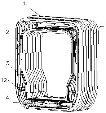
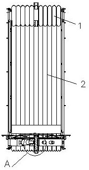
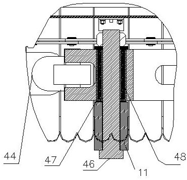
[0036] like Figure 1-Figure 9 As shown, a suspension train car end connection system includes an outer bellows 1, an inner bellows 2, a floor composition 3 and a hinge device 4, the inner bellows 2 is a "Ji"-shaped structure with an opening at the lower end, and the outer bellows 1 The middle frame 11 is provided to fix and support the entire outer bellows 1 to prevent the outer bellows 1 from sagging; Both ends of the bellows 1 and the inner bellows 2 are fixedly connected to the ends of the two adjacent compartments, the outer bellows 1 and the inner bellows 2 are connected by fixed rods 12, the middle frame 11 and the middle inner frame 21 It is also connected by the fixed rod 12. In this embodiment, the upper and lower parts of the inner bellows 2 and the outer bellows 1 are connected by the fixed rods 12 to ensure the consistency of the positions between the outer bellows 1 and the inner bellows 2 . Of course, the position of the fixing rod 12 can also be set according...

Embodiment 2

[0041] In this embodiment, for the vehicle type with a coupler on the top of the vehicle body, the top of the middle frame 11 can also be fixed to the vehicle body through the coupler, that is, the middle frame 11 is fixed to the vehicle body through the upper and lower positions to further ensure the stability of the passageway sex.

[0042] It can be seen from the above embodiments that the present invention also relates to a method for connecting the ends of suspended trains. The outer bellows 1 is divided into two parts by the middle frame 11, and the inner bellows 2 is also divided into two parts by the middle inner frame 21, so that the inner bellows 2 can be divided into two parts. Extend the length of the bellows without causing the bellows to sag due to gravity, and ensure that the suspended vehicles can smoothly realize the small-radius curve movement without interference. A hinged device 4 with a vibration-damping structure is arranged below the floor composition 3,...


PUM


Abstract

A method and system for connecting the ends of a suspended train, in which a hinged device with a vibration-damping structure is provided below the floor composition of the joint, and the two ends are respectively connected to adjacent carriages, and the middle position of the lower part of the middle frame is fixed on the lower part of the middle frame through the suspension device The center of rotation of the hinged device ensures that the centerline of the bellows is consistent with the centerline of the vehicle during the operation of the vehicle. At the same time, the two transition plates composed of the floor are placed under the part above the floor in the compartment, the ground height of the joint is raised, and the space between the bottom of the floor and the middle frame is increased to ensure smooth fixing between the hinge device and the middle frame. The lower end of the middle frame is fixed on the car body through a hinged device, so that the middle frame, which plays a supporting role in the process of vehicle vibration and curve passing, will not shake, ensuring the stability of the vehicle and satisfying the dynamic performance.

Description

technical field [0001] The invention relates to a car end connection method and system, in particular to a car end connection method and system for connecting two adjacent carriages of a suspended train. Background technique [0002] The train is composed of multiple carriages connected. The connection structure between the carriages is called a through passage. The through passage must ensure the close connection of adjacent carriages, prevent the intrusion of wind and rain, and provide a safe and comfortable passage for passengers; At the same time, the passageway is also a flexible and movable part of the train, which ensures the stability between the two connected cars when the train vibrates when turning. And for trains in different operating environments and different operating modes, they have different requirements for the design of the passageway. Usually, the composition of the through passage includes: bellows composition, top plate mounting seat, top guard plate...

Claims


Application Information

Patent Timeline
Patent Type & Authority Patents(China)
IPC IPC(8): B61B3/00B61B12/04
CPCB61B3/00B61B12/04
Inventor 罗斌贺小龙庄征宇胡伟辉雷军玉林胜刘文松
Owner ZHUZHOU TIMES NEW MATERIALS TECH
Learn More